
Method for maximizing the energy output of a wind turbine

a technology of wind turbine and energy output, applied in the direction of propellers, water-acting propulsive elements, and optimizing machine performance, etc., can solve the problems of unavoidable deviations from the ideal, complex installation, and large investment in such wind turbines

Inactive Publication Date: 2006-09-05
WOBBEN ALOYS
View PDF12 Cites 28 Cited by
  • Summary
  • Abstract
  • Description
  • Claims
  • Application Information

AI Technical Summary

Benefits of technology

[0011]To avoid a situation in which constant variation of an operational setting ultimately causes even greater loss of yield, these variations are performed at predefinable time intervals so that whenever an optimal setting has been found, this is then maintained for a predefined period.
[0014]A particularly preferred embodiment of the method according to the invention is one in which the difference between the initial setting and the varied setting with the optimal yield is quantified and taken into consideration for subsequent changes and / or variations. In this way, the time needed for variation and hence for reaching the maximum yield can be shortened.

Problems solved by technology

The continuous development of wind turbines has led to them becoming complex installations in which many parameters and settings must be inter-coordinated to enable optimised operation.
Owing to the high complexity of wind turbines and the enormous costs involved in developing and refining them, purchasing such a wind turbine requires considerable amounts of money.
However, this profit is inseparably linked to the power yield of a wind turbine, which is why maximization of power yield has an understandably high priority, especially for the owner and / or the operator of such a turbine.
On the other hand, in all production processes generally, and given the complexity of wind turbine and their dimensions, deviations from the ideal are unavoidable.
Regardless of the question as to whether such deviations are actually acceptable or not, they always signify a loss of yield in that they imply a divergence from the optimal arrangement.

Method used


Image

  • Method for maximizing the energy output of a wind turbine
  • Method for maximizing the energy output of a wind turbine
  • Method for maximizing the energy output of a wind turbine

Examples


Embodiment Construction

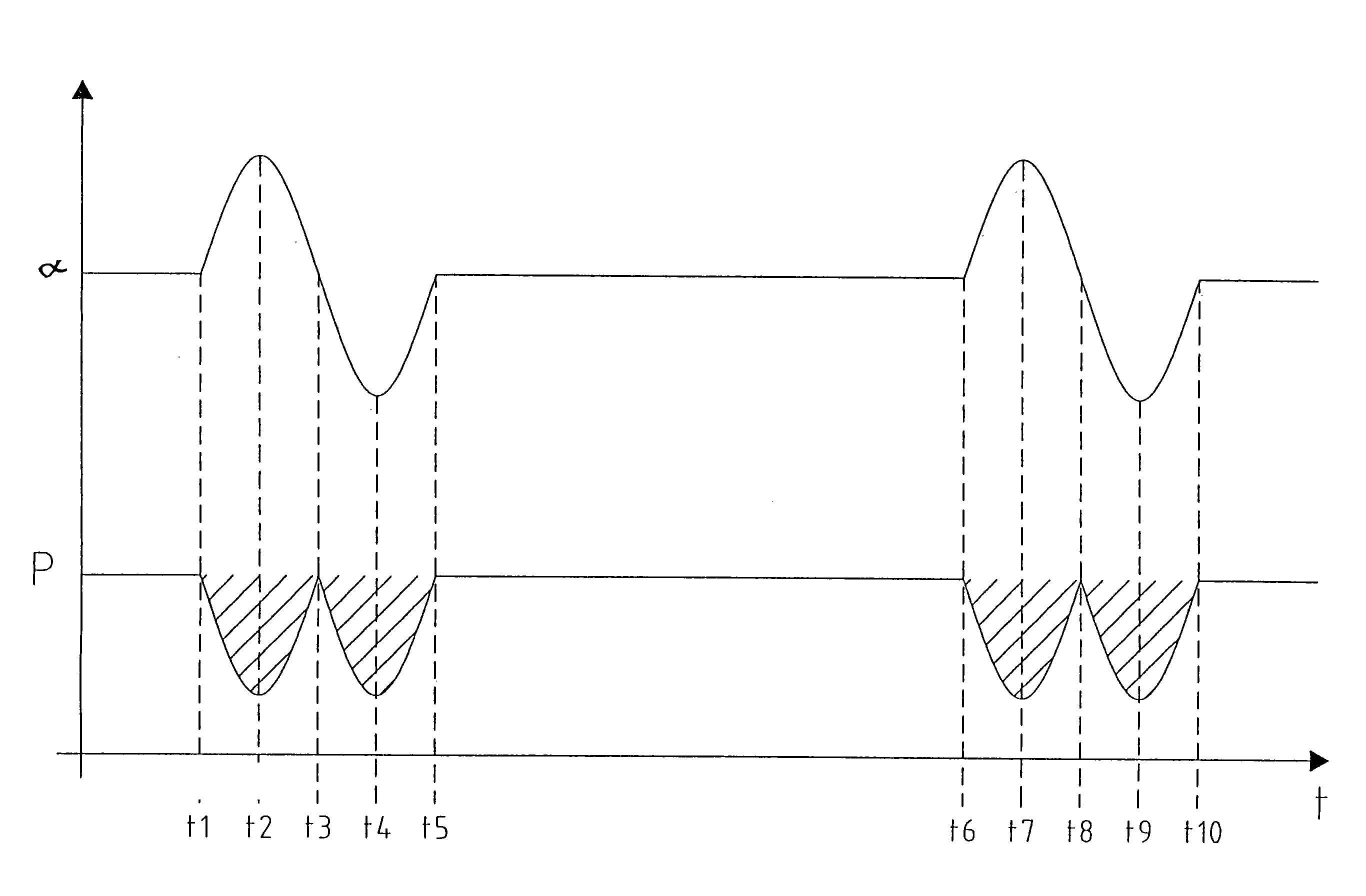
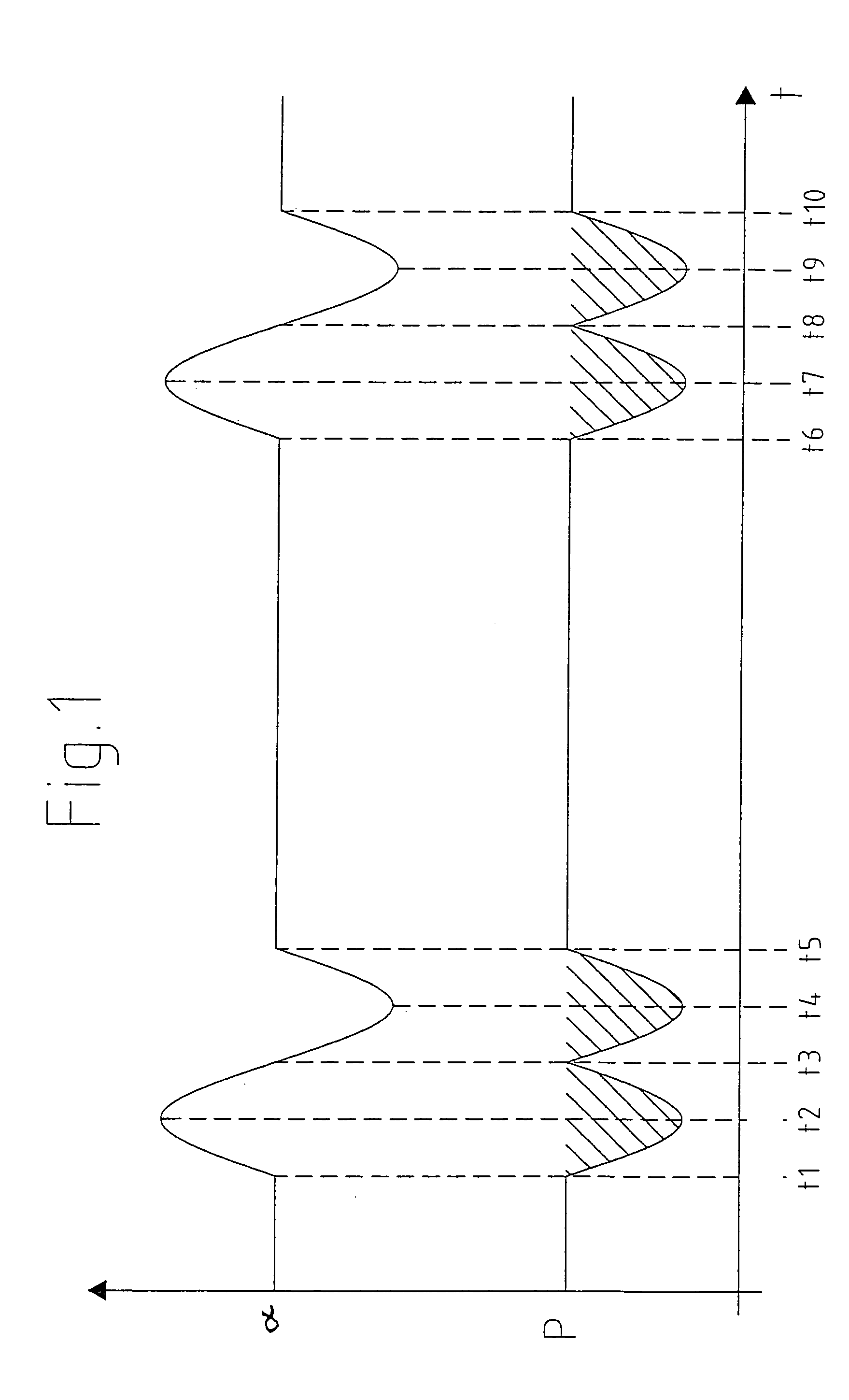
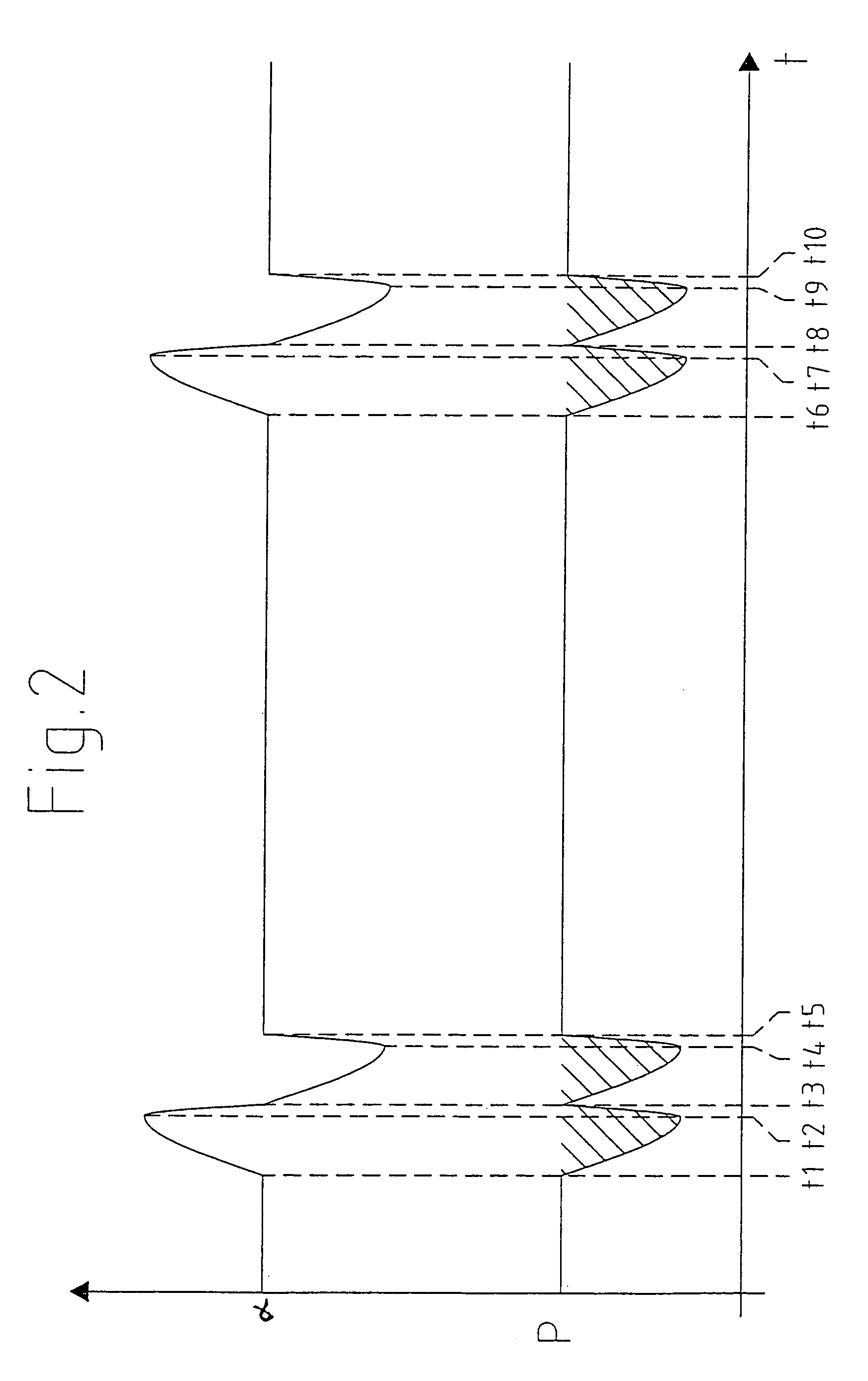
[0023]FIG. 1 illustrates the basic principle of the method of the invention for controlling a wind turbine. In the Figure, time t is plotted on the x-axis, the upper portion of the y-axis is used to plot the variation of an operational setting, for example the azimuth angle (α) of the nacelle and hence of the wind turbine rotor, and the lower portion shows, in simplified form for the sake of clarity, the variation in power yield in the form of a power curve (P).

[0024]It can be seen from the upper curve that variation of the operational setting out of its starting position begins initially in a positive direction and with a sinusoidal waveform at time t1, reaches a maximum value at time t2 and at time t3 has returned to the initial value. From there, variation is continued in the opposite direction, reaching a maximum at time t4, and at time t5 has again returned to the initial value.

[0025]If an increase in power yield now occurs during such variation, the operational setting may be ...


PUM


Abstract

A method is provided for controlling a wind turbine, and a wind turbine is provided with a control device for controlling a wind turbine. A method and a wind turbine are developed so that losses of yield, particularly as a result of variations in the conversion of the kinetic energy of the wind into electrical energy, e.g., in the rotor, drive train and generator, are minimized as far as possible. A method is provided for controlling a wind turbine, wherein at least one operational setting is varied within predefined limits.

Description

TECHNICAL FIELD[0001]The present invention relates to a method for controlling a wind turbine and to a wind turbine with a control device for controlling a wind turbine.BACKGROUND OF THE INVENTION[0002]Wind turbine with controllers have been generally known for years and are now deployed with success. The controller, especially, has a major influence on the energy yield of a wind turbine.[0003]The continuous development of wind turbines has led to them becoming complex installations in which many parameters and settings must be inter-coordinated to enable optimised operation.[0004]Owing to the high complexity of wind turbines and the enormous costs involved in developing and refining them, purchasing such a wind turbine requires considerable amounts of money. It is easily understandable that such expenses are acceptable only if the wind turbines permit the maximum amount of profit to be generated, in addition to amortization of the investment, from the operating revenues obtained du...

Claims


Application Information

Patent Timeline
IPC IPC(8): F03D7/04F03D9/00
CPCF03D7/046Y02E10/723F05B2270/20Y02E10/72F03D7/00
Inventor WOBBEN, ALOYS
Owner WOBBEN ALOYS
Learn More