
Dishwasher having spray arms and a circulation pump

a technology of circulation pump and dishwasher, which is applied in the direction of positive displacement liquid engine, liquid fuel engine, and washing using liquids, can solve the problems of foam formation and detrimental to washing, and achieve the effect of high hydraulic efficiency

Inactive Publication Date: 2006-09-05
MIELE & CIE KG
View PDF23 Cites 56 Cited by
  • Summary
  • Abstract
  • Description
  • Claims
  • Application Information

AI Technical Summary

Benefits of technology

[0007]Before the backdrop of the above-mentioned state of the art, it is an object of the present invention to provide a flow system—consisting of the water diverter and the pump system—of a dishwasher of the afore-mentioned type in such a way that it achieves a high degree of hydraulic efficiency.
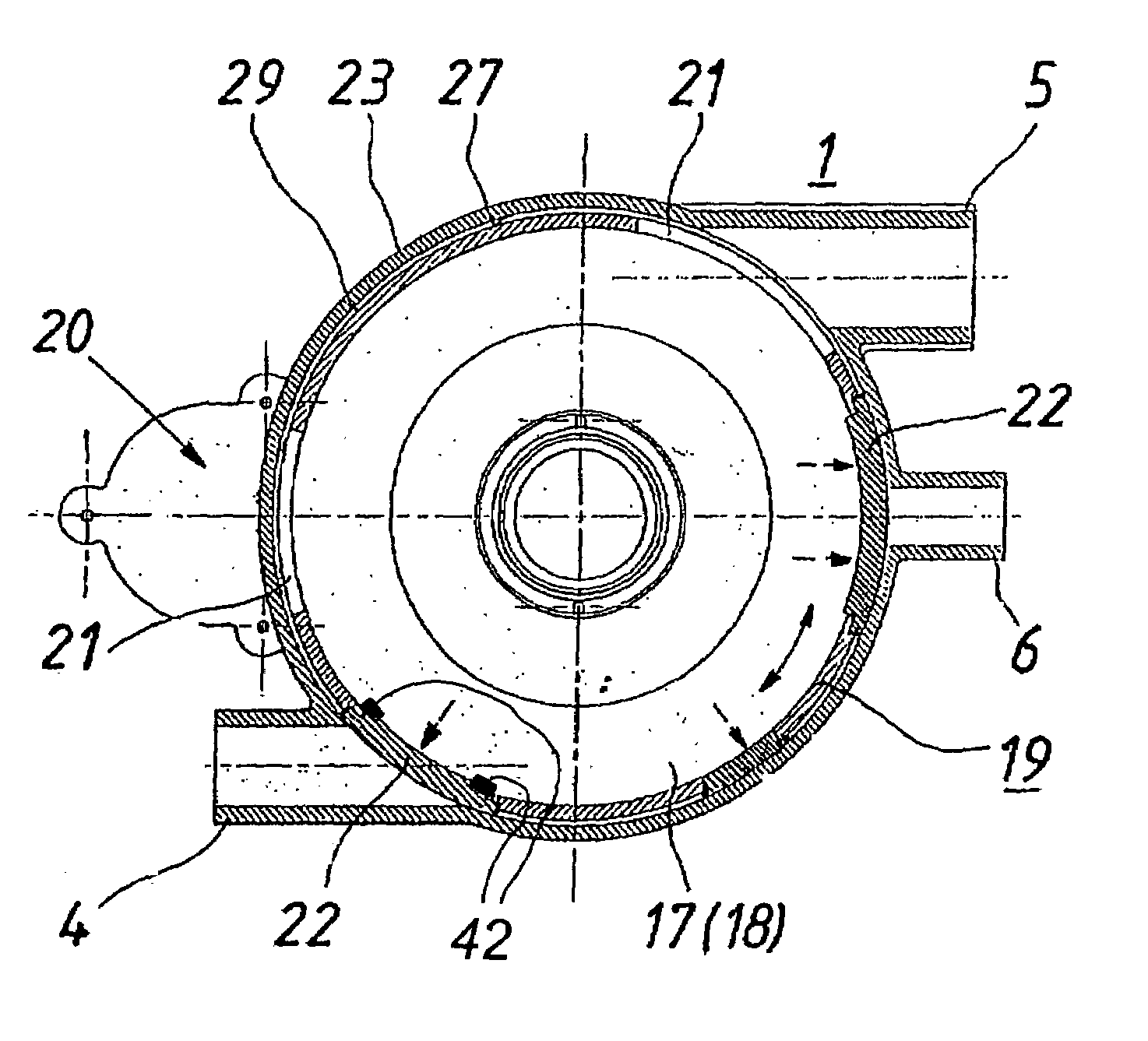
[0009]This brings about the advantage that the design and dead volume of the circulation pump, combined with that of the water diverter, is almost the same as in a circulation pump without a water diverter. Accordingly, it becomes possible to save construction space in this already crowded device and to increase the degree of hydraulic efficiency in the device. Furthermore, there is no need for connecting lines between the pump and the water diverter. Turning the blocking element in its circumferential direction does not generate strong forces since the direction of rotation is not opposite to the pump pressure. For this reason, in an advantageous manner, the water diverter can be made of relatively inexpensive materials whose strength requirements are low.
[0010]In an advantageous embodiment, the diaphragm openings of the blocking element and the openings of the discharge ports are selected in such a way that the cross-sectional areas of all of the discharge ports opened by the blocking element remain constant in total, even while the blocking element is being turned to one of the outlet positions. Since the cross-sectional areas remain constant, the pump delivers a constant circulation volume, thus preventing air from being sucked in, which would lead to foam formation and, in turn, be detrimental for the washing results. Moreover, the fact that the circulation volume remains constant keeps the noise level constant during operation.

Problems solved by technology

Since the cross-sectional areas remain constant, the pump delivers a constant circulation volume, thus preventing air from being sucked in, which would lead to foam formation and, in turn, be detrimental for the washing results.

Method used


Image

  • Dishwasher having spray arms and a circulation pump
  • Dishwasher having spray arms and a circulation pump
  • Dishwasher having spray arms and a circulation pump

Examples


Embodiment Construction

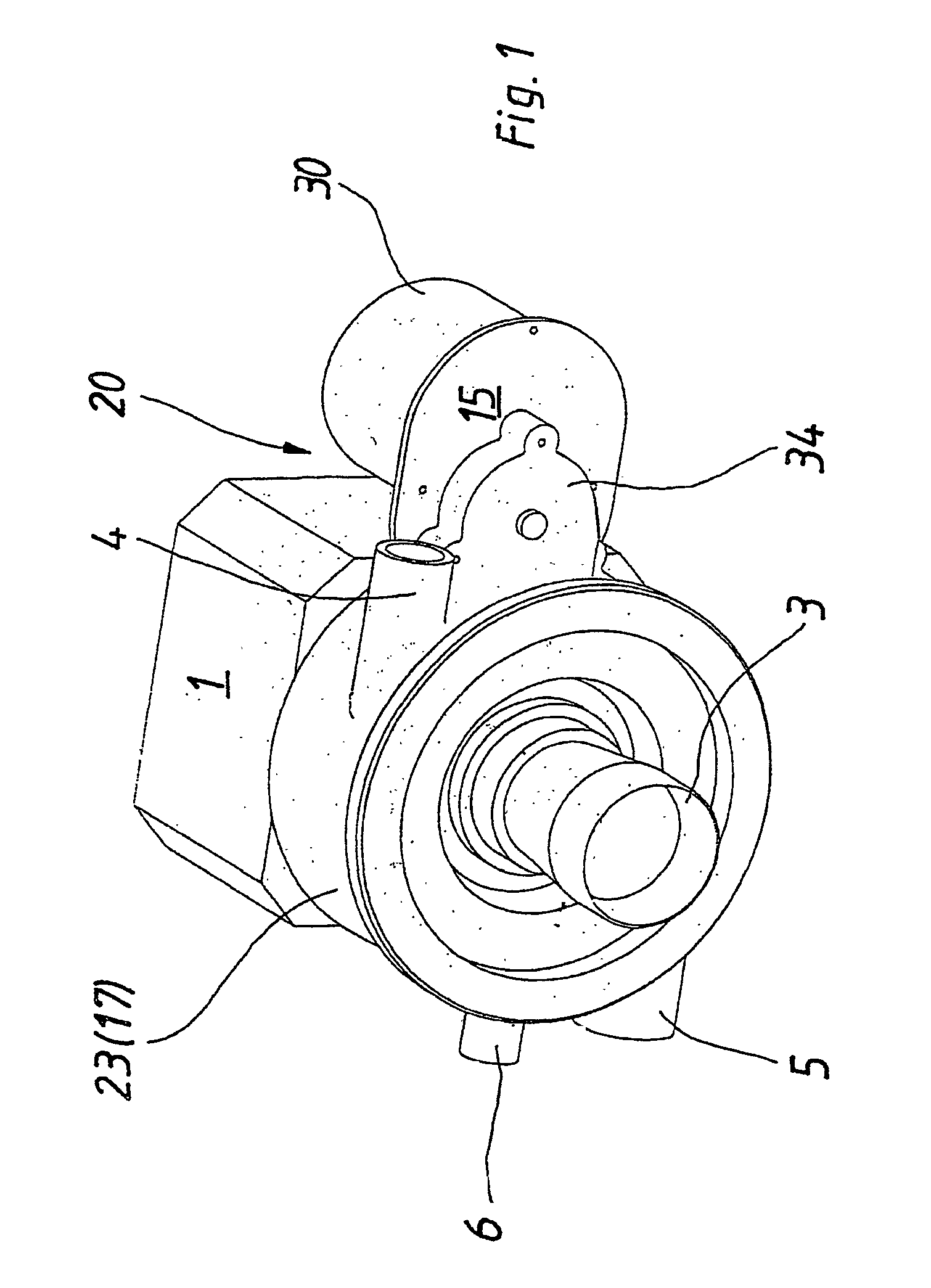
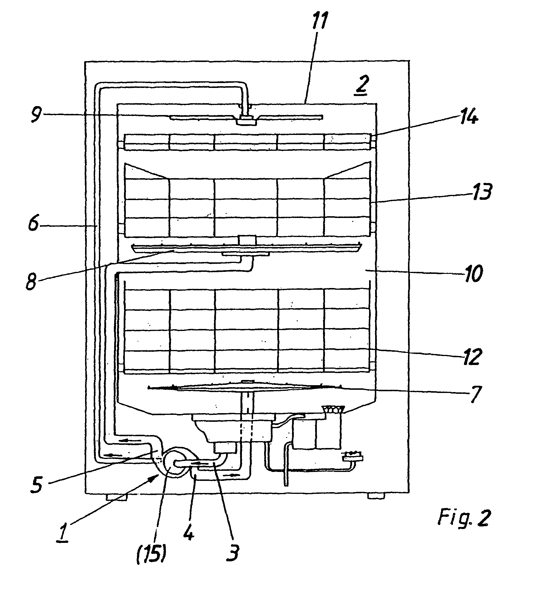
[0024]A circulation pump (1) depicted in FIG. 1, especially for a dishwasher (2), see FIG. 2, has a suction port (3) for washing solution and three separate discharge ports (4, 5, 6) on the pump housing (23), which are to be connected to the associated spray arm feed lines so that the spray arms (7, 8, 9) of the dishwasher (2) schematically shown in FIG. 2 can be filled with the washing solution.

[0025]By means of the circulation pump (1) configured as a centrifugal pump, the washing solution in the dishwasher (2) is circulated by pumping it out of the washing tub (10) and then back into it again via the three spray arms (7 to 9) of the system and over the items to be washed. Here, each spray arm (7, 8 or 9) is associated with a separate discharge port (4, 5 or 6) of the circulation pump (1). Thus, for example, the spray arm (7) associated with the lower rack (12) is supplied with washing or cleaning solution by the discharge port (4) while the upper rack (13) for dishes is supplied ...


PUM


Abstract

A dishwasher includes a number of spray arms, a circulation pump with a pump housing, an impeller, a suction port, and a number of discharge ports on the pump housing. The discharge ports are associated with the spray arms. A water diverter is located on a delivery side of the pump and generates a flow leading from the suction port selectably to one or more of the discharge ports. The water diverter includes a blocking element having a number of diaphragm openings positionable to one or more outlet positions by a drive via a rotation of the blocking element in a circumferential direction.

Description

[0001]The present invention relates to a dishwasher with spray arms and with a circulation pump, having an impeller, a suction port and at least one discharge port on the pump housing, with a water diverter provided on the delivery side of the pump in order to generate a flow leading from an inlet to one of several selectable outlets associated with the spray arms, whereby the water diverter has a blocking element with at least one diaphragm opening that can be positioned by a drive in at least one outlet position.BACKGROUND[0002]The circulation pumps employed in devices through which water flows, particularly for conveying washing water in dishwashers used in households or in industry, are normally centrifugal pumps which are mounted at the bottom of the washing tub. Such a pump serves to circulate the washing solution by pumping it out of the washing tub and then back into it again through the spray arms of the system and over the items to be washed. In this context, for purposes ...

Claims


Application Information

Patent Timeline
Patent Type & Authority Patents(United States)
IPC IPC(8): B08B3/00F04B19/00A47L15/23A47L15/42F04D15/00F16K11/085F16K15/18
CPCA47L15/4221A47L15/4225F04D15/0016F16K11/0853F16K15/188A47L15/4285A47L15/0049Y10S415/911Y10T137/86501F16K15/1848
Inventor ASSMANN, WALTERHETTENHAUSEN, ULRICHMARKS, VOLKER
Owner MIELE & CIE KG
Learn More