
Photonic home area network

a home area network and photonic technology, applied in the field of bidirectional routing of devices, can solve the problems of inability to accommodate varying data formats, inability to meet the needs of individual households, and periodic high fees for having television, telephone, internet or other communication services provided to their homes

Inactive Publication Date: 2006-08-29
THROUGHPUT HLDG
View PDF23 Cites 22 Cited by
  • Summary
  • Abstract
  • Description
  • Claims
  • Application Information

AI Technical Summary

Benefits of technology

[0020]Drawings of a preferred embodiment of the invention are annexed he...

Problems solved by technology

Individuals are periodically charged expensive fees to have television, telephone, Internet, or other communications services provided to their homes.
However, available neighborhood network technology has insufficient bandwidth to accommodate all the data associated with television, telephone and other communications services, making a neighborhood network impractical and expensive.
Furthermore, such network systems do not accommodate varying data formats such as synchronous transmissions typical of television transmissions, and asynchronous transmission typical of computer data transmissions.
For example, present network broadcasts of video are generally limited to unidirectional distribution
A problem with such a device is that it is limited to distributing data and does not allow the addition of data by users.
A further problem is that data is limited to synchronous transmissions.
Upstart companies have been denied access to potential customers in these markets because landlords have existing service arrangements with the regional Bell companies.
Further, building owners do not desire dozens of start-up companies traipsing onto their properties.
The upstarts, known as competitive local-exchange carriers or CLECs, complain that competition is inhibited without their access inside the buildings.
Commonly, the upstarts' requests to enter buildings are often turned down, and even when allowed to come in, the negotiation process is prolonged or landlords demand excessive fees.
On the other hand, allowing access to the building is burdensome to the building owner.
It has not been practical to allow access in view that, in Florida for example there are over 250 suppliers, which would wreak havoc if there was a building with over 400 renters.
An example has been with SONET, which requires optical signals travelling across the network to be converted into electrical signals at each network transit point, and then re-converted into optical signals for transport to the next transit point: The multiple conversions required in a SONET / SDH network increase network complexity and cost.
But SONET / SDH has been cumbersome.
As a result, moving data through the network involves the complex processes that add cost and make scaling difficult.
Unlike voice traffic, which is generally characterized by slow growth and stable demand, rapid growth and unpredictable demand characterize data traffic.
But the SONET / SDH network architecture has not been sufficiently flexible to meet present data requirements.
Generally expanding the capacity of a SONET / SDH network is time-consuming and requires significant capital investment by the service provider.
Accordingly, adding capacity to a SONET / SDH ring network has been a complex and time-consuming process.
Under either approach, network complexity increases since each optical wavelength must be terminated by SONET / SDH equipment and the interconnection of multiple SONET / SDH rings will absorb some available network capacity

Method used


Image

  • Photonic home area network
  • Photonic home area network
  • Photonic home area network

Examples


second embodiment

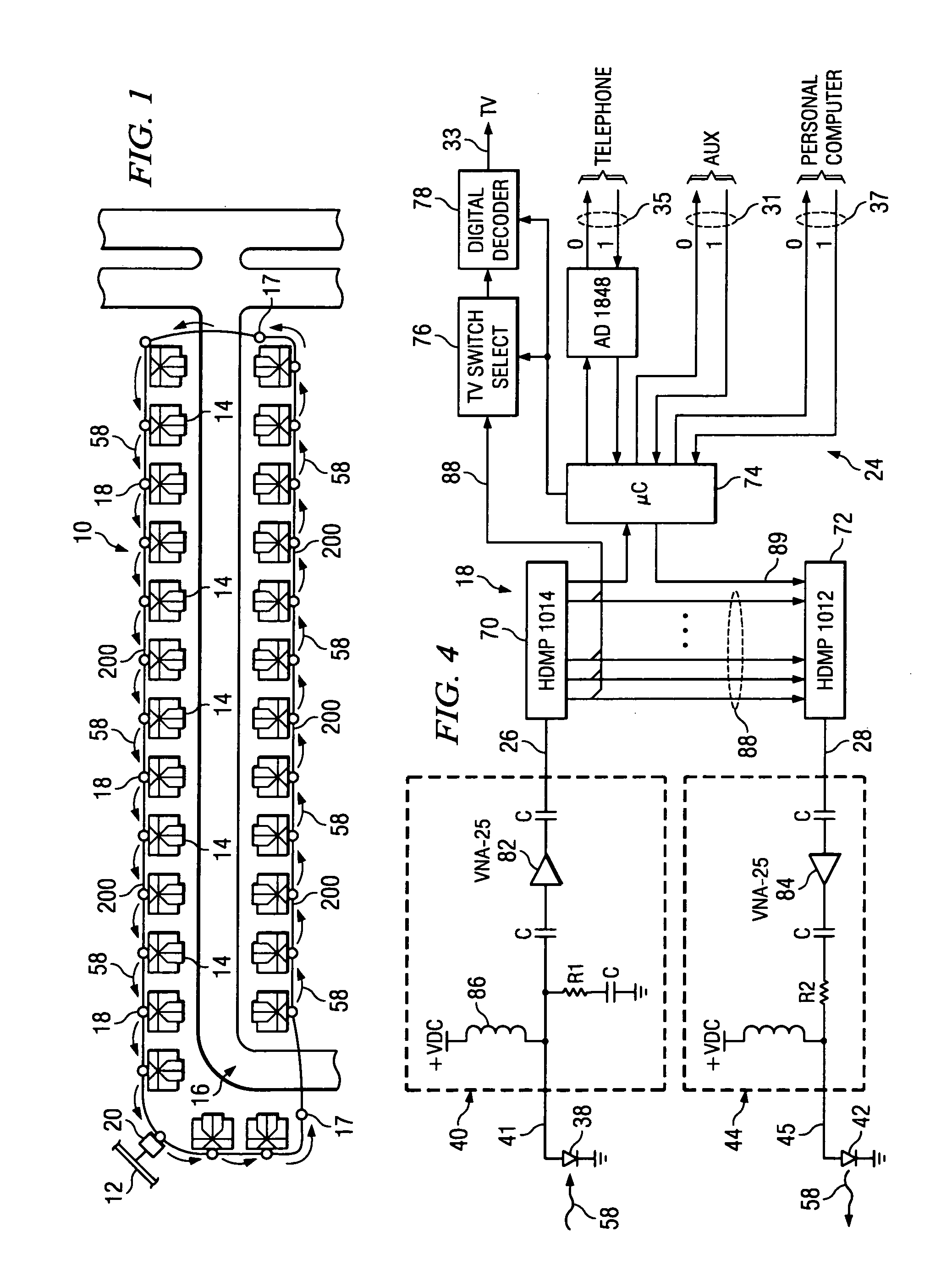
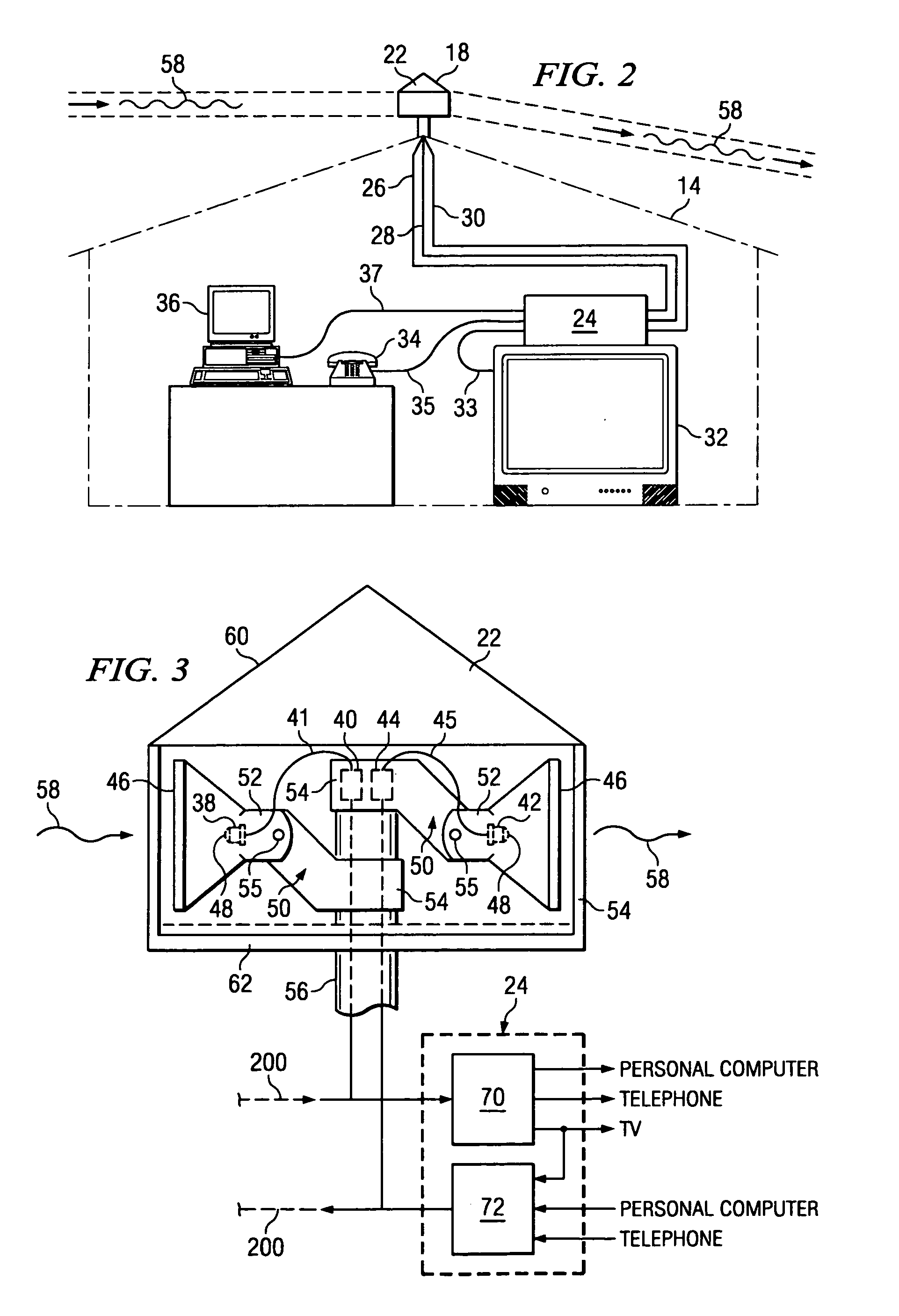
[0071]Redundancy can be designed into the HAN 10 with a bi-directional path. For example, when a node station 18 in the HAN 10 is interrupted, data flow can be re-routed such that each side of the photonic network interruption is self-contained. Hardware redundancy in the set-top box and in the transmit optical laser 42 and the receive optical detector 38 can be installed using the same principles as disclosed above.

[0072]A redundant-path roof-top unit 300 is illustrated in FIG. 9. For clarity, one receive and transmit configuration is shown. Another such configuration is mounted substantially opposite the illustrated unit so that the network ring can be completed. Redundant-path roof-top unit 300 of would require the position of the laser 42 and the detector 38 to be complementary arranged for the laser at one location to optically couple to the detector at the other location and vice versa. If a link or photonic path 58 is blocked, the information can be looped back to the head-en...

further embodiment

[0075]A data cell-based, or packet-based, embodiment of the set-top box, or service node card 400, is provided to take advantage of cell-based information routing. Such a data configuration allows expeditious routing of data in cell formats that can be conducted through the routing devices, such as Field Programmable Gate Arrays (“FPGA”) executing firmware routines for expeditious routing of data.

[0076]The service node card 400 preferably implements a data cell format that can be provided as through use of Asynchronous Transmission Medium (“ATM”) format. An ATM cell is 53 bytes in length, with five bytes allocated for addressing purposes under the field designation ADDR. Generally, one byte may be allocated for checksum purposes, however, this one byte may be used for other informational purposes. The address portion of the cell contains “data type” information that is placed by the head end with respect to the particular node structure of the network.

[0077]The ADDR field contains a...


PUM


Abstract

An apparatus for a service node used in a multimedia network. The apparatus has a data distributor circuit, and a decoder. The data distributor card has a data port for coupling with a data stream. The data distributor circuit has a relational code for determining whether an address field of a data packet of the data stream is intended for local distribution to peripheral devices by the distribution circuit. The decoder, in communication with the distribution circuit, has a virtual channel filter for filtering the address field to route the data packet to at least one data port, such as that associated with a peripheral device. An incorporator circuit is provided that is electrically-coupled to the data port to insert an address value having a relational code and a virtual channel code in a data input from the at least one data port. The incorporator then inserts the data input from the at leas tone data port into the data stream. In a method of the invention, interfacing a multimedia communications data stream having a plurality of data packets is provided. Inputing a data packet of the data stream, determining whether an address field of the data packet is intended for local distribution, and routing the data packet to a data port if the data packet is intended for local distribution. Otherwise, the data packet is returned to the data stream if the data packet is not intended for local distribution.

Description

RELATED APPLICATIONS[0001]This is a continuation-in-part of U.S. Nonprovisional application Ser. No. 08 / 607,964, entitled Photonic Home Area Network, filed Feb. 29, 1996, now U.S. Pat. No. 5,983,068 to John L. Tomich, et al., which is incorporated herein by reference for all purposes. This continuation-in-part further claims the benefit of U.S. Nonprovisional application Ser. No. 08 / 607,964 filed Feb. 29, 1996.TECHNICAL FIELD[0002]The present invention relates to a device for bi-directional routing of data for a plurality of dissimilar electronic devices, and in particular, to data routing for a plurality of dissimilar electronic devices from a common data path.BACKGROUND OF THE INVENTION[0003]Individuals are periodically charged expensive fees to have television, telephone, Internet, or other communications services provided to their homes. If these individuals could be formed into a network group, then the resulting economic leverage of these networked individuals create a better ...

Claims


Application Information

Patent Timeline
IPC IPC(8): H04L12/28G06F15/16H04N7/18H04Q11/00
CPCH04L12/2803H04L12/2834H04Q11/0067H04L12/2852H04L12/2838H04Q2011/0073H04Q11/0071
Inventor TOMICH, JOHN L.VONAHNEN, MICHAEL J.SHEEHAN, MICHAEL B.
Owner THROUGHPUT HLDG
Learn More