
Traffic-driven wind generator

a technology of wind generators and traffic, applied in the direction of electric generator control, renewable energy generation, greenhouse gas reduction, etc., can solve the problems of inability to describe the use of high-speed vehicular applications, small fraction of the air output of vehicular traffic can be captured, and inability to du

Active Publication Date: 2006-08-29
WIEGEL THEODORE F +1
View PDF23 Cites 102 Cited by
  • Summary
  • Abstract
  • Description
  • Claims
  • Application Information

AI Technical Summary

Benefits of technology

The system effectively doubles traditional energy output by capturing high-speed winds from vehicular and train traffic, providing stable and durable energy generation with minimal maintenance, and can integrate with existing infrastructure for efficient energy conversion and distribution.

Problems solved by technology

However, it does not appear to describe its use in high-speed vehicular applications.
However, because of the limited surface area it presents to vehicles, only a small fraction of the air output from vehicular traffic can be captured.
Also, ducting is not practical, and the unshrouded design causes concern for safety.
Further, the use of Savonius-type wind generators designed for either horizontal or vertical mounting is not known in the art.

Method used


Image

  • Traffic-driven wind generator
  • Traffic-driven wind generator
  • Traffic-driven wind generator

Examples


Embodiment Construction

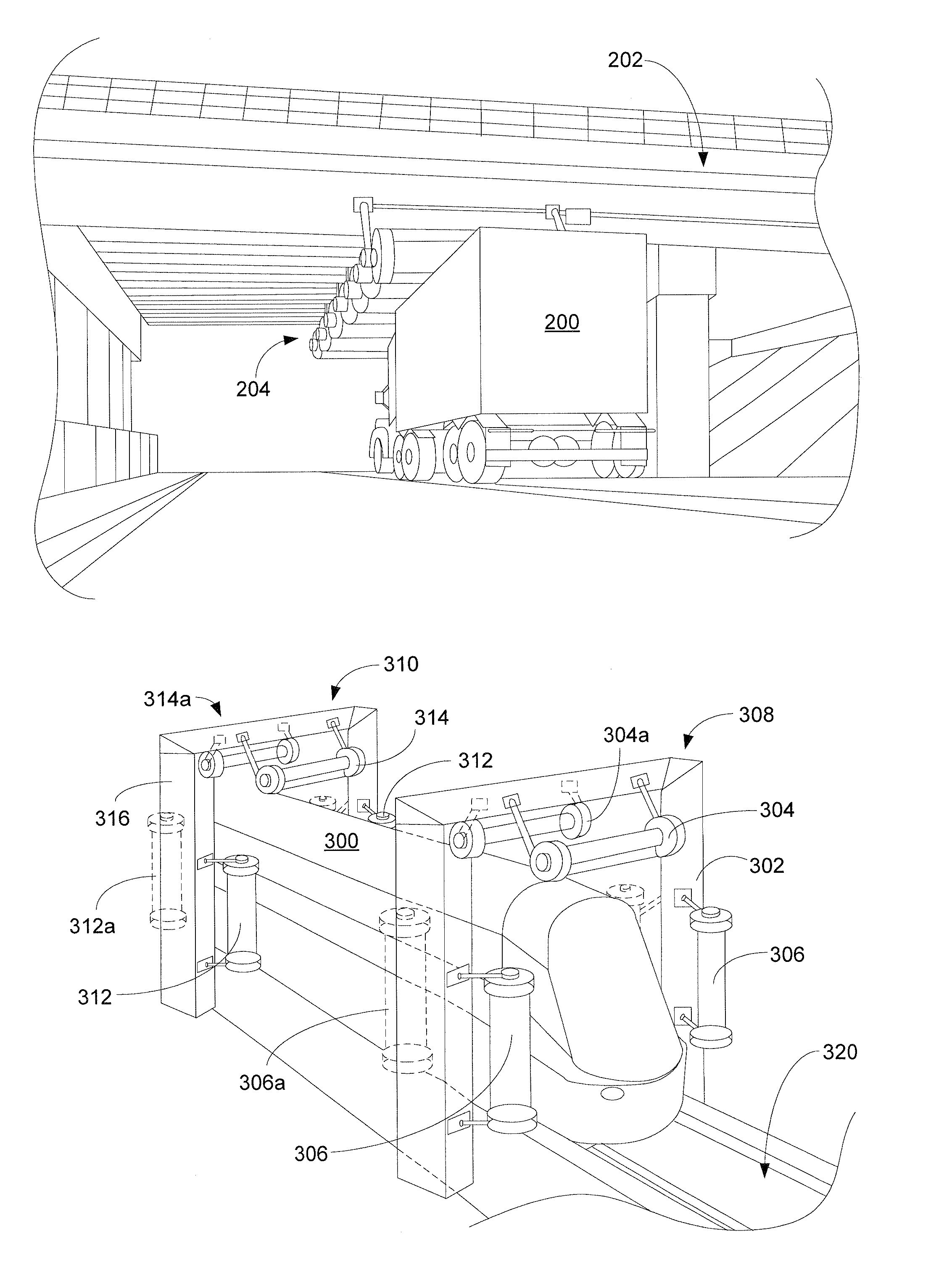
[0016]While this invention is illustrated and described in a preferred embodiment, the device may be produced in many different configurations, forms and materials. Depicted in the drawings and herein described in detail is a preferred embodiment of the invention, with the understanding that the present disclosure is to be considered an exemplification of the principles of the invention and the associated functional specifications for its construction, and is not intended to limit the invention to the embodiment illustrated. Those skilled in the art will envision many other possible variations within the scope of the present invention.

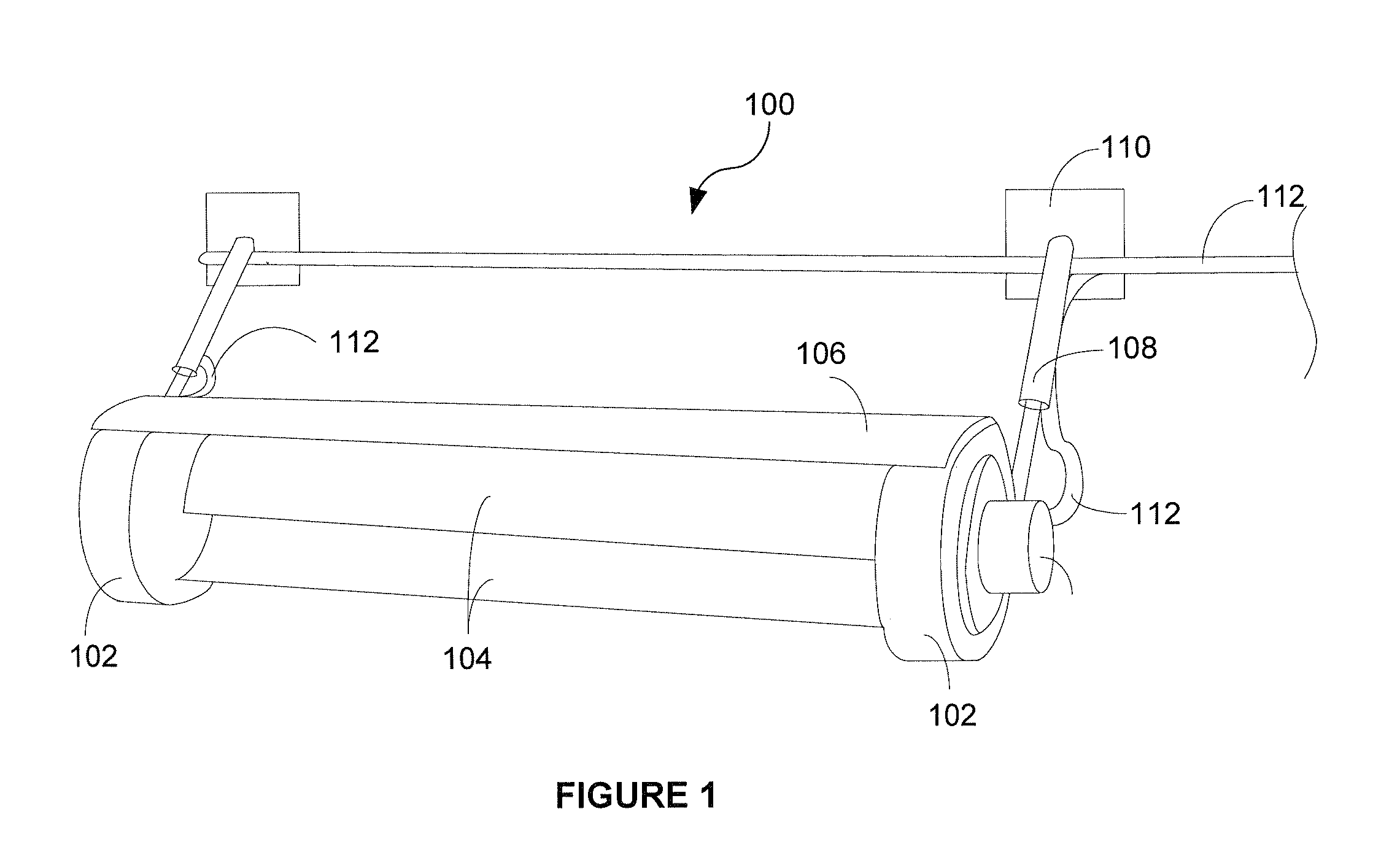
[0017]FIG. 1 illustrates general wind-capturing device 100 used in the present invention. As shown, device 100 is preferably a horizontally-mounted Savonius-type wind generator. Device 100 comprises variable-speed electrical generators 102 and energy-capturing vanes 104 that are of the Savonius-type or helical-turbine type. Although two generators and ...


PUM


Abstract

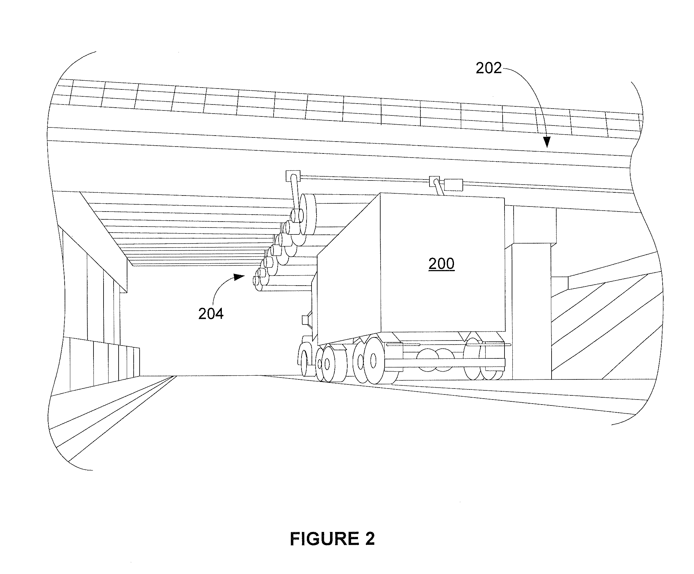
A wind-capturing electrical generator device comprising a plurality of generators is driven by wind created by traffic passing in close proximity at high speeds. The device preferably uses horizontally or vertically mounted Savonius-type or helical-turbine-type rotors attached to electrical generators in order to capture the wind and produce electrical energy. A plurality of electrical generator devices may be mounted in a configuration such that they are in close proximity to vehicular passageways (e.g., highway overpasses, tunnels, or train rails). The wind created by the traffic is used to rotate the vanes and their attached generators in order to produce electrical energy.

Description

BACKGROUND OF THE INVENTION[0001]The present invention relates generally to the field of alternative energy production. More specifically, the present invention is related to wind-driven electrical generators.[0002]One form of alternative energy production is wind generators, which are sometimes referred to as wind turbines. Wind generators may be categorized into two general types: those with a horizontal turning shaft—or on a horizontal axis—that point into the wind, or those with a vertical shaft—or on a vertical axis—that point vertically (or upward). Horizontal-axis generators are the most common kind of wind turbine. The blades or vanes provided on the horizontal-axis type are lifted aerodynamically as the wind blows into the device, causing the shaft to turn. Alternately, the vertical-axis type, such as a Savonius wind generator, generally comprises two vanes that catch the wind, thus causing the vertical shaft to turn. For example, see U.S. Pat. No. 1,766,765, which disclose...

Claims


Application Information

Patent Timeline
Patent Type & Authority Patents(United States)
IPC IPC(8): F03D9/00H02P9/04
CPCF03D3/002F03D9/002F05B2220/602F05B2240/213Y02E10/728F05B2240/9113F05B2250/25Y02E10/74F05B2240/2212F03D9/25Y02B10/30F03D9/46F03D13/20F03D80/70F03D3/02
Inventor WIEGEL, THEODORE FSTEVENS, KENNETH C
Owner WIEGEL THEODORE F
Learn More