
Fine-grained fill reinforcing apparatus and method

Inactive Publication Date: 2006-08-29
MEGA
View PDF24 Cites 36 Cited by
  • Summary
  • Abstract
  • Description
  • Claims
  • Application Information

AI Technical Summary

Benefits of technology

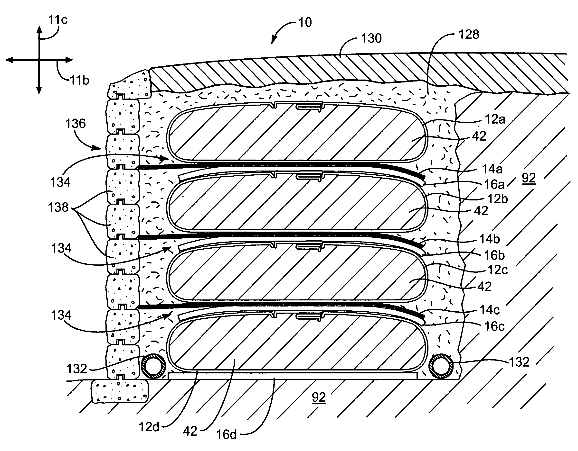
[0011]In operation, the containers may confine, strengthen, and drain the earthen material contained therein. If desired or necessary, drain layers may be placed underneath and between the various containers. The drain layers may accelerate evacuation of any water held within the containers. Suitable drain layers may include sand, gravel, conduits, geogrids, geonets, specially designed geocomposite drains, or combinations thereof.
[0022]Moreover, the use of multiple containers or structures permits higher embankment heights and widths. Structural members anchored to the containers may support facing materials, which protect the structure as well as strengthening the roadway during construction. In such applications, additives (e.g. cement, sand) may be introduced while filling the containers to control final structural properties. If desired, the initial layer of geotextile tubes or containers can be left unamended to allow sufficient flexibility to settle with the underlying soft foundation.

Problems solved by technology

Fine-grain fill has low particle-to-particle frictional interaction and thus, little inherent ability to resist shear loads.
Fine-grained fill is typically not included in the design and construction of geosynthetic reinforcements (e.g. retaining walls, berms, breakers, road beds, causeways, etc.) because of its low shear strength and the potential for settlement, slope failure, bulging failure, and creep.
For example, the amount of fine-grained fill currently tolerated behind modern reinforced retaining walls is strictly limited.
In general, granular fill is more expensive than fine-grained fill.
The cost associated with such transportation may be high, and occasionally prohibitive.

Method used


Image

  • Fine-grained fill reinforcing apparatus and method
  • Fine-grained fill reinforcing apparatus and method
  • Fine-grained fill reinforcing apparatus and method

Examples


Embodiment Construction

[0039]It will be readily understood that the components of the present invention, as generally described and illustrated in the drawings herein, could be arranged and designed in a wide variety of different configurations. Thus, the following more detailed description of the embodiments of the system and method of the present invention, as represented in the drawings, is not intended to limit the scope of the invention, as claimed, but is merely representative of various embodiments of the invention. The illustrated embodiments of the invention will be best understood by reference to the drawings, wherein like parts are designated by like numerals throughout.

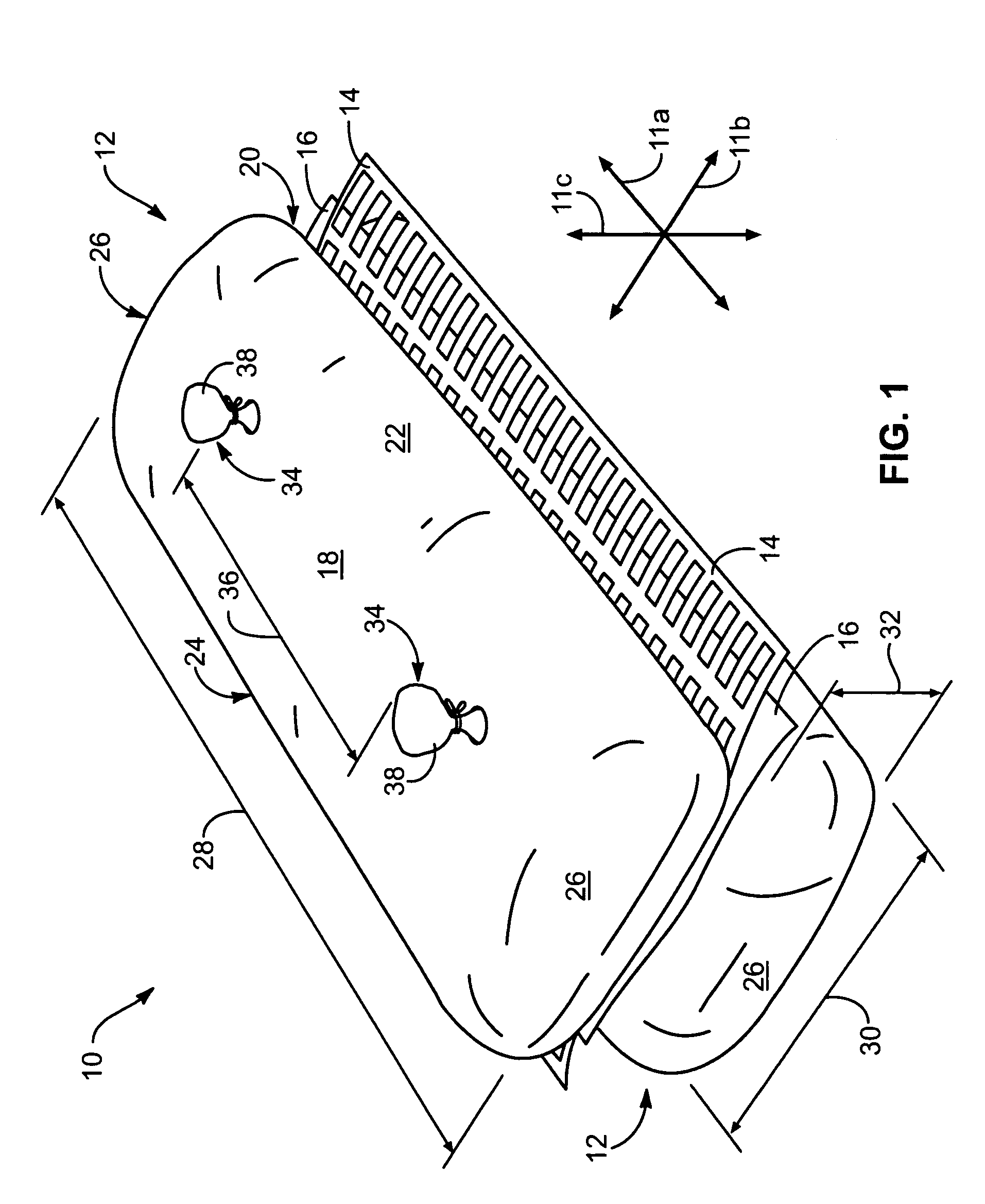
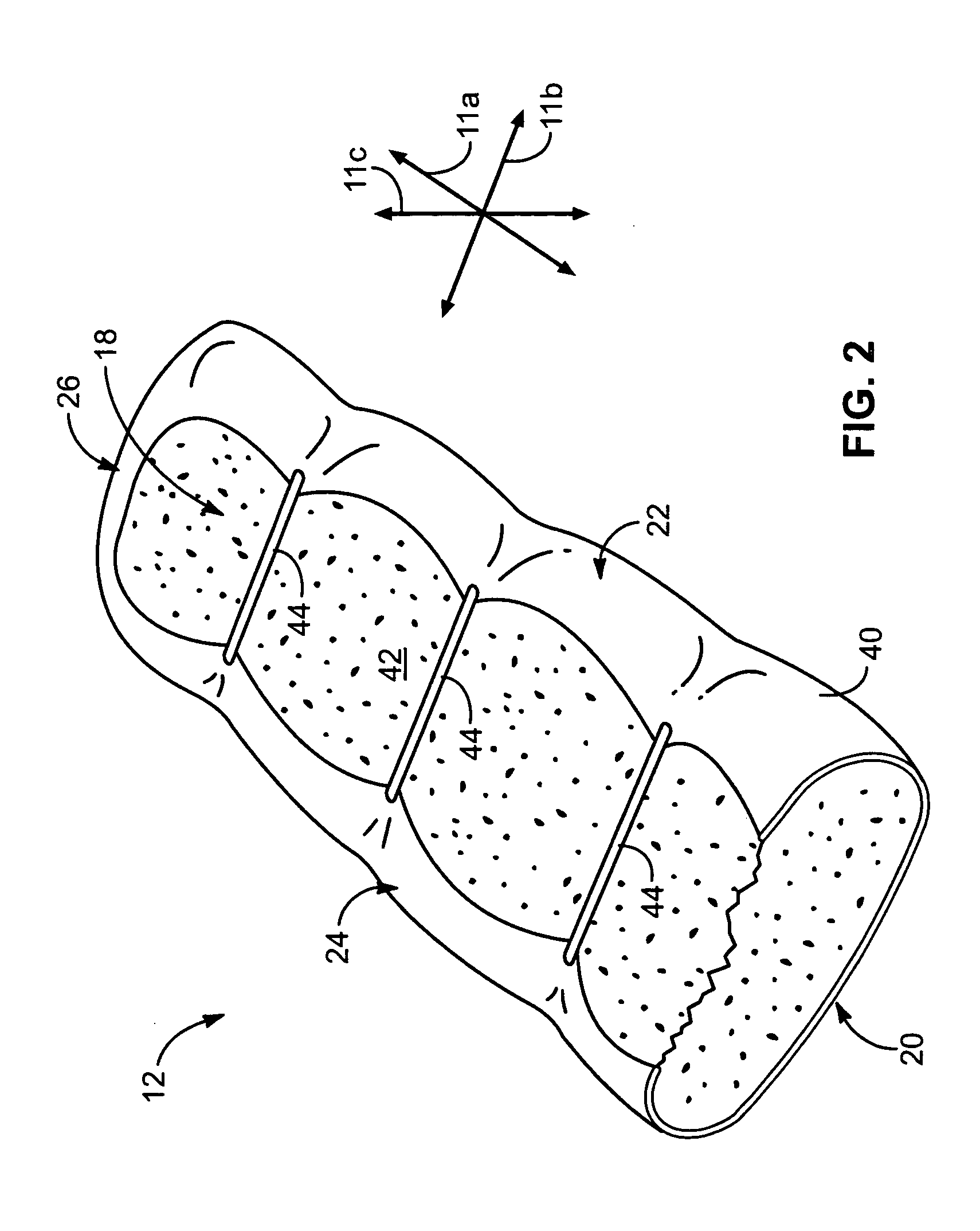
[0040]Referring to FIG. 1, a geosynthetic reinforcement 10 in accordance with the present invention may define longitudinal 11a, lateral 11b, and transverse directions 11c substantially orthogonal to one another. In selected embodiments, a geosynthetic reinforcement 10 may include one or more containers 12, one or more structura...


PUM


Abstract

A geosynthetic reinforcement comprising a container formed of semipermeable material mutually conformed with a portion of earthen material contained therein. A structural member such as a geogrid may engage (e.g. frictional) the container and extend therefrom to engage and support a structure such as a retaining wall, earthen slope, etc. Accordingly, the container may function as an anchor to the structure. Due to the containment provided by the container, the physical characteristics of the earthen material therewithin become less important. Thus, low quality fills such as fine-grained fill or fill with a high moisture content may be used in structural applications. If desired, more than one container and structural member may be incorporated. Containers may be stacked, positioned side-by-side, positioned end-to-end, etc. Structural members may be incorporated as needed to adequate support the structure. Drain layers may be incorporated to control moisture. In some cases, containers may comprise geotextile tubes.

Description

BACKGROUND[0001]1. The Field of the Invention[0002]This invention relates to geosynthetic reinforcements for reinforced earthwork construction and, more particularly, to novel systems and methods for using fine-grained fill in structural applications.[0003]2. The Background Art[0004]In general, earthen fills may be divided into two groups, namely granular and fine-grained. Granular fill such as gravel, coarse sand, fine sand, and the like is sometimes referred to as cohesionless fill. Granular fill has an inherent ability to resist shear loads. Fine-grained fill, on the other hand, is often referred to as cohesive fill because it is held together primarily by cohesion between particles. Fine-grain fill has low particle-to-particle frictional interaction and thus, little inherent ability to resist shear loads. Examples of fine-grained fill include silt and clay.[0005]Fine-grained fill is typically not included in the design and construction of geosynthetic reinforcements (e.g. retain...

Claims


Application Information

Patent Timeline
IPC IPC(8): E02D3/00E02D29/02
CPCE02D29/0208E02B3/127
Inventor MOSS, ARTHUR L.
Owner MEGA
Learn More