Spurious free dynamic range in optical communications systems

a free dynamic range and optical communication technology, applied in the field of optical transmitters, can solve the problems of spurious noise on the optical link connecting the optical transmitter, spurious noise generated by the interaction of the laser included in the transmitter with the rest of the optical link,

Inactive Publication Date: 2006-08-22
CISCO TECH INC
View PDF2 Cites 6 Cited by
  • Summary
  • Abstract
  • Description
  • Claims
  • Application Information

AI Technical Summary

Problems solved by technology

It is well known in the art that spurious noise exists on the optical link connecting the optical transmitter and the optical receiver.
More specifically, spurious noise is generated from the interaction of the laser included in the transmitter with the rest of the optical link.
Spurious noise, therefore, affects both data signals and video signals.
Optical attenuation can be used to reduce, but not eliminate, spurious noise, however, at the cost of reduced optical power.
Disadvantageously, however, the cost of an isolator is expensive and sometimes exceeds that of the laser.
As a result, in-band intermodulation products are disadvantageously generated as the channel loading increases.
Additionally, the composite power of the dithering tones reduces the system dynamic range available to desired signals.
Dithering tones are not recommended, however, when video carrier signals are present because the dithering tones affect the viewing quality and signal processing of the video signals.

Method used


Image

  • Spurious free dynamic range in optical communications systems
  • Spurious free dynamic range in optical communications systems
  • Spurious free dynamic range in optical communications systems

Examples


Embodiment Construction

[0013]The present invention will be described more fully hereinafter with reference to the accompanying drawings in which like numerals represent like elements throughout the several figures, and in which exemplary embodiments of the invention are shown. This invention may, however, be embodied in many different forms and should not be construed as being limited to the embodiments set forth herein; rather, the embodiments are provided so that this disclosure will be thorough and complete, and will fully convey the scope of the invention to those skilled in the art. For example, the present invention is explained relative to the reverse path of a communications system; however, the present invention can also be used in the forward path. The present invention is described more fully hereinbelow.

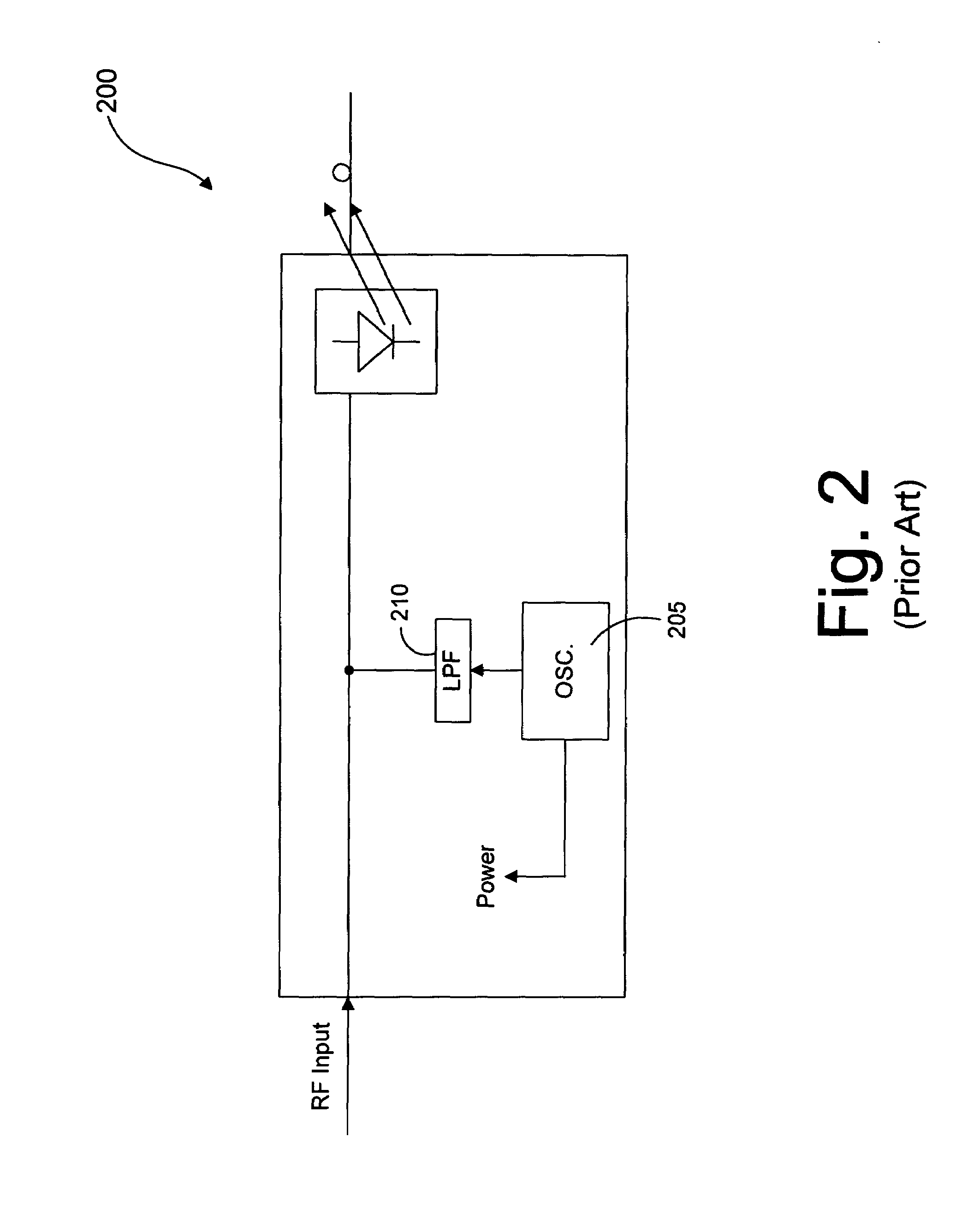
[0014]The present invention is directed towards replacing the oscillator 205 (FIG. 2) with a noise generator. The noise generator provides filtered noise signals that are combined with the RF s...


PUM


Abstract

The present invention is directed towards an optical transmitter including a noise generator. The noise generator provides noise signals that are filtered to below a frequency spectrum. The filtered noise signals are combined with RF signals to provide continuous modulation of a laser. The combined signals are converted to optical signals by the laser and transmitted over an optical link.

Description

FIELD OF THE INVENTION[0001]This invention relates generally to broadband communications systems, such as cable television networks, and more specifically to an optical transmitter including a spurious noise mitigator circuit that is suitable for use in the broadband communications system.BACKGROUND OF THE INVENTION[0002]FIG. 1 is a block diagram illustrating an example of one branch of a conventional broadband communications system, such as a two-way hybrid / fiber coaxial (HFC) network, that carries optical and electrical signals. Such a network may be used in a variety of systems, including, for example, cable television networks, voice delivery networks, and data delivery networks to name but a few. The communications system 100 includes headend equipment 105 for generating forward, or downstream, signals (e.g., voice, audio, video, or data signals) that are transmitted to subscriber equipment 145. Initially, the forward signals are transmitted via optical transmitters (not shown)...

Claims


Application Information

Patent Timeline
Patent Type & Authority Patents(United States)
IPC IPC(8): H04B10/00H04B10/155
CPCH04B10/504H04B10/2575H04B10/58
Inventor QUESENBERRY, PAUL E.AL-ARAJI, SALEH R.BRUMLEY, JR., EDWARD W.
Owner CISCO TECH INC
Why Eureka
Try Eureka