
System, apparatus, and method of conducting borehole resistivity measurements

a technology of resistivity measurement and system, applied in the direction of fluid resistance measurement, measurement device, instruments, etc., can solve the problems of uncontrollable influx of formation fluid, large expense in addressing unsafe conditions, and well-known blowou

Active Publication Date: 2006-08-22
SCHLUMBERGER TECH CORP
View PDF10 Cites 30 Cited by
  • Summary
  • Abstract
  • Description
  • Claims
  • Application Information

AI Technical Summary

Benefits of technology

[0020]FIG. 8 is a simplified diagram of an alternative log

Problems solved by technology

If the pressure differential is relatively large, the influx of formation fluids may be uncontrollable.
This presents a danger of a well “blowout, which is of particular concern when the formation fluids include flammable hydrocarbons.
Moreover, considerable expense is incurred in addressing the unsafe condition and restoring the well to a stable, and then operable condition.
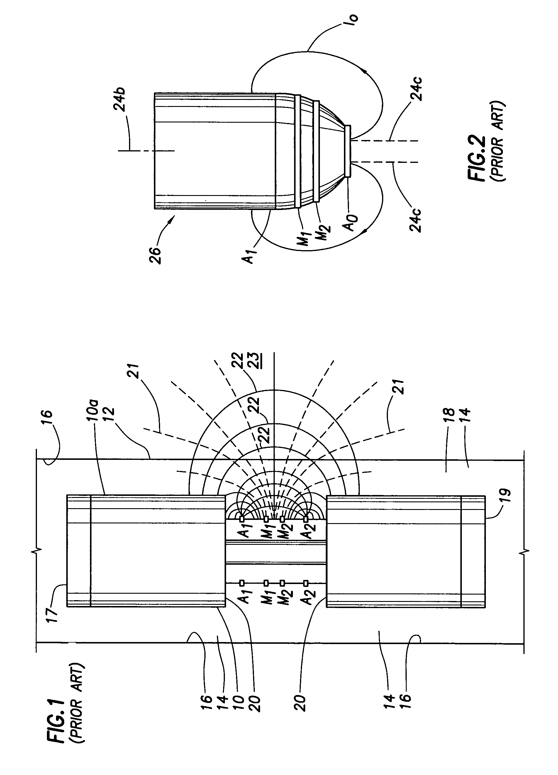
The heads 17 and 19, which must withstand a high mud external pressure, are each very expensive to manufacture, costing about ten thousand dollars each.
However, a problem exists: the voltage potential drop in region 23 of FIG. 1 is actually representative of the resistivity of both the mud 18 and the formation penetrated by the wellbore 12.
Therefore, when using the AMS sub of FIG. 1, the adverse effect of the crossing current 22 on the mud resistivity (Rm) measurement still exists and, as a result, the mud resistivity measurement is not as accurate as desired.

Method used


Image

  • System, apparatus, and method of conducting borehole resistivity measurements
  • System, apparatus, and method of conducting borehole resistivity measurements
  • System, apparatus, and method of conducting borehole resistivity measurements

Examples


Embodiment Construction

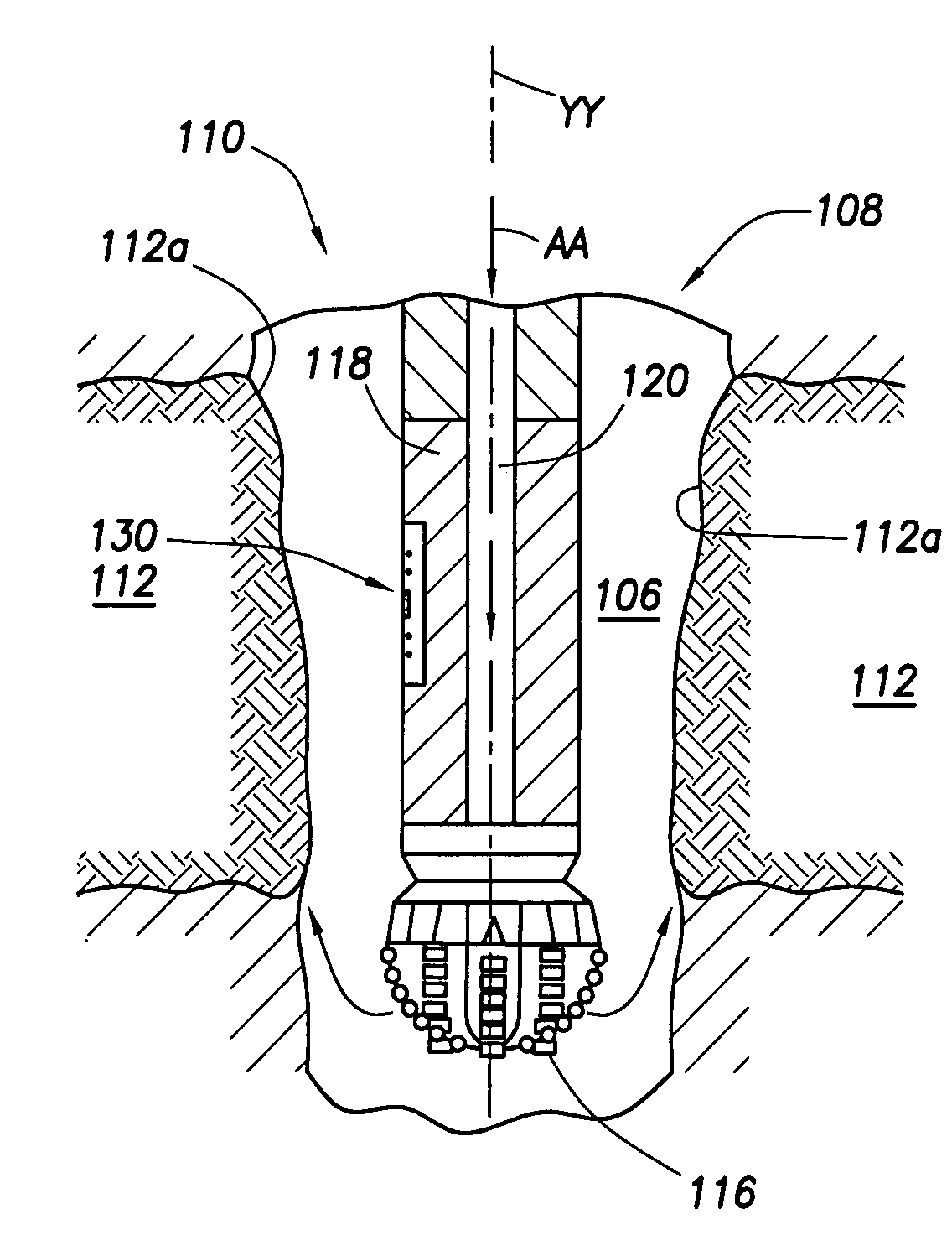
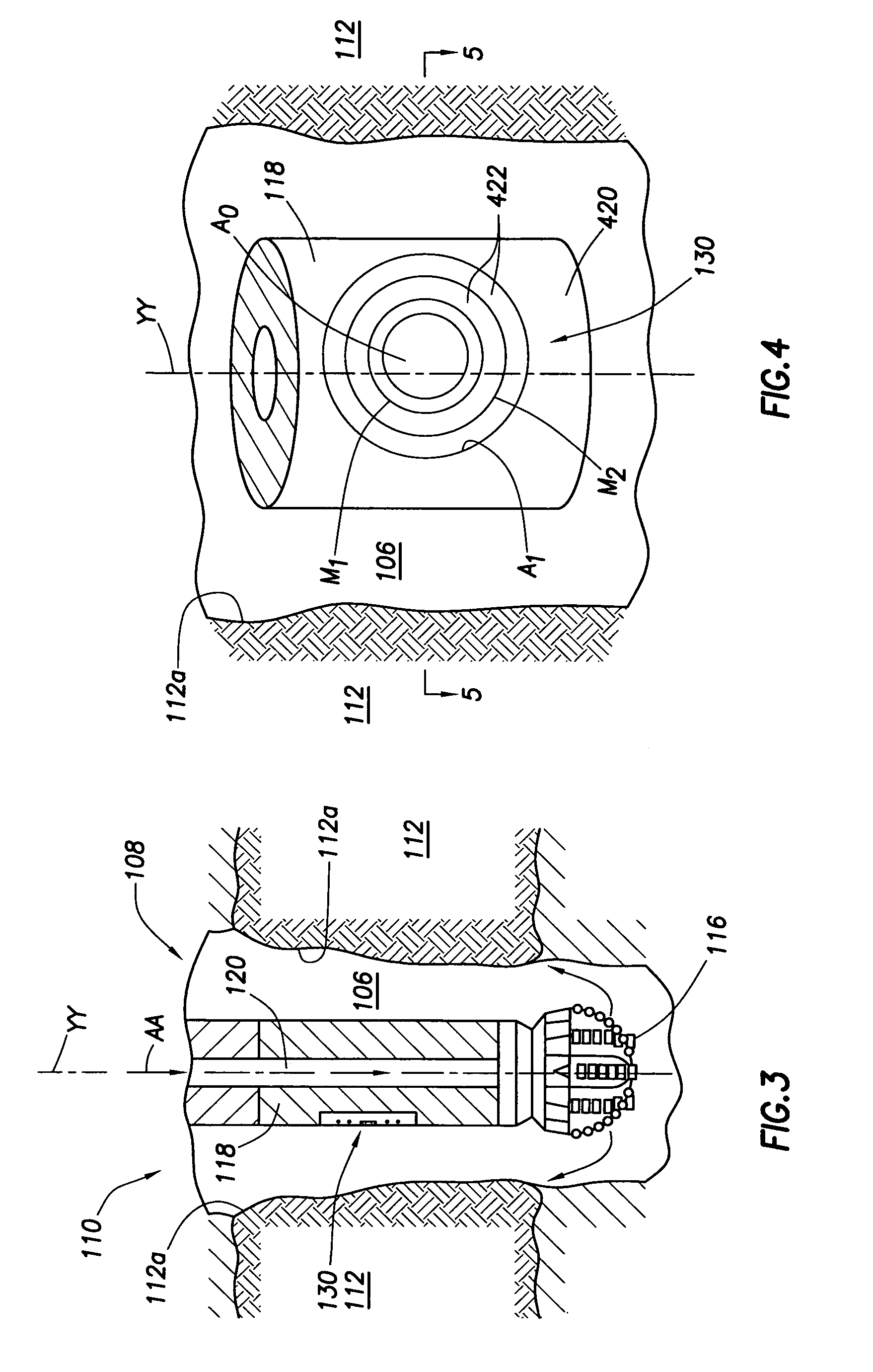
[0028]The present invention is particularly suited for use with a logging-while-drilling (LWD) tool or apparatus. FIGS. 3–9 depict LWD tools embodying various aspects of the invention. It should be noted, however, that the measurement system and drilling tool illustrated in the Figures and / or described herein are provided to illustrate exemplary applications of the invention. It will become apparent to one generally skilled in the relevant petrophysical, mechanical, electrical, and other relevant art, upon a viewing of the present disclosure, that various aspects of the invention are applicable to other types of wellbore tools (e.g., wireline and coil tubing tools) and other structures and other configurations. The present invention should not, therefore, be limited to the specific structures and methods described herein.

[0029]Referring to FIG. 3, a section of a drill string 108 is depicted situated in a wellbore 110 penetrating a geological formation 112 of interest. The section of...


PUM


Abstract

A logging-while-drilling tool is adapted for incorporation with a drill string having a longitudinal axis. The drill string is further adapted for drilling a wellbore penetrating a geological formation. The drilling tool includes a tool body having a central axis disposed in parallel relation with the longitudinal axis of the drill string and an external, circumferential surface spaced radially outward from the central axis. The tool also includes a measurement apparatus for measuring resistivity of a borehole fluid in the wellbore. The measurement apparatus has an electrode array including a current emitting electrode disposed on the circumferential surface. The current emitting electrode is adapted to emit current into a target region of the wellbore spaced laterally between the circumferential surface and the walls of the wellbore. Further, a current receiving electrode is disposed on the circumferential surface and spaced apart from the current emitting electrode. The current receiving electrode is adapted to receive current propagated from the current emitting electrode into the target region. The electrode array occupies an arcuate section of the circumferential surface that extends less than about 180° about the central axis.

Description

BACKGROUND[0001]The present invention relates generally to the drilling and exploration of a geological formation for the ultimate purpose of extracting hydrocarbons therefrom. More particularly, the invention relates to a system, apparatus, and method of conducting measurements from a wellbore or borehole penetrating the formation. The inventive system, apparatus, and method described herein are particularly suited for measuring a resistivity of a conductive formation fluid or mud in the borehole.[0002]Formation fluids typically enter the borehole when the pressure in the formation exceeds the hydrostatic pressure. If the pressure differential is relatively large, the influx of formation fluids may be uncontrollable. This presents a danger of a well “blowout, which is of particular concern when the formation fluids include flammable hydrocarbons. Moreover, considerable expense is incurred in addressing the unsafe condition and restoring the well to a stable, and then operable condi...

Claims


Application Information

Patent Timeline
IPC IPC(8): G01V3/20G01V3/00G01V3/18
CPCG01V3/20G01R27/22
Inventor TABANOU, JACQUES R.MORRISS, CHRISTOPHER E.
Owner SCHLUMBERGER TECH CORP
Learn More