
Multiple supply gate array backfill structure

a backfill structure and gate array technology, applied in the field of application specific integrated circuits, can solve the problems of long turnaround time, high cost of preparing a full mask set that accommodates design modifications, and cannot guarantee that the appropriate circuit is available in the correct location

Inactive Publication Date: 2006-08-22
IBM CORP
View PDF15 Cites 12 Cited by
  • Summary
  • Abstract
  • Description
  • Claims
  • Application Information

AI Technical Summary

Problems solved by technology

Despite advanced design software packages, however, it is often necessary to modify the original layout after manufacture to address logic design problems.
Unfortunately, preparing a full mask set that accommodates design modifications is expensive and creates long turnaround times prior to getting the fixed parts.
This technique, however, does not guarantee that the appropriate circuit will be available in the correct location when a modification is required.
The use of voltage islands, however, presents a variety of problems relative to the conventional modification techniques discussed above.
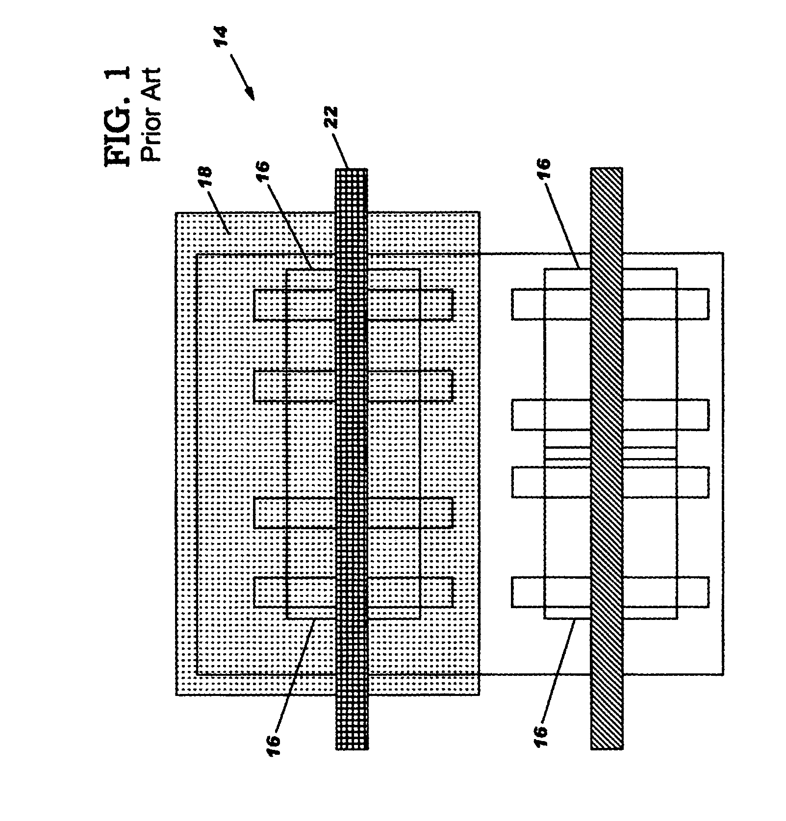
In particular, while typical gate array backfill cell structures 14 are usable to correct problems within voltage islands, they are unusable where an interconnection physically crosses over a voltage island or crosses a voltage island boundary because of the voltage differences involved.
Unfortunately, it is impossible to place a buffer circuit into a voltage island in most cases because the buffer circuit up-level is referenced to the wrong voltage, i.e., the voltage of the voltage island.
Accordingly, if a modification requires, for example, an interconnection of voltage islands or a signal inversion across a voltage island, current modification technology is incapable of implementation.

Method used


Image

  • Multiple supply gate array backfill structure
  • Multiple supply gate array backfill structure
  • Multiple supply gate array backfill structure

Examples


Embodiment Construction

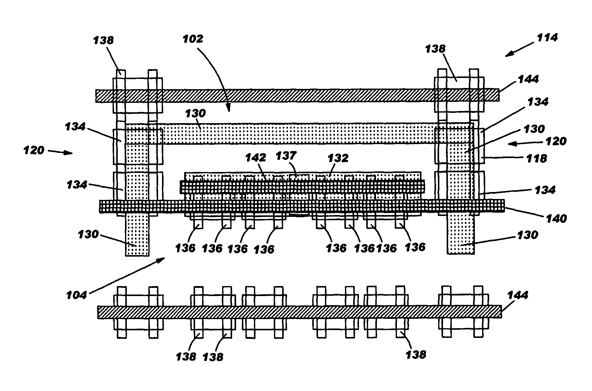
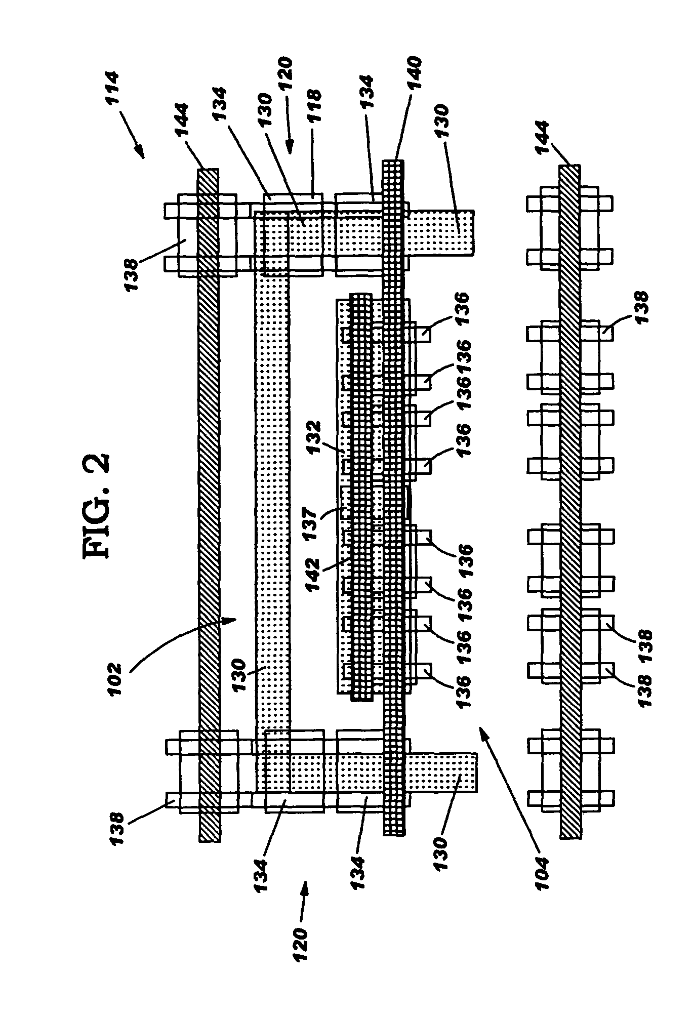
[0021]With reference to the accompanying drawings, FIG. 2 shows a gate array backfill structure 114 (hereinafter backfill structure) of the invention. Backfill structure 114 is designed to be placed in unused space of an IC for implementing changes in IC function. Backfill structure 114 includes a first voltage domain 102 and a second voltage domain 104. First voltage domain 102 includes a shred n-well 130 that is shared between every two adjacent rows on boundaries 120, and a first transistor set 134 built upon and connected to shred n-well 130. Second voltage domain 104 includes an isolated n-well 132 that is not shared between two adjacent rows on boundaries 120, and is isolated from shared n-well 130, and a second transistor set 136 built upon and connected to isolated n-well 132. A first voltage terminal 140 extends over both shared n-well 130 and isolated n-well 132, and is connected to at least shared n-well 130 (interconnection to n-well 130 not shown for clarity). A second ...


PUM


Abstract

A multiple supply gate array structure facilitated by the provision of a shared n-well and an isolated n-well is described. The gate array structure allows implementation of a single voltage circuit or a multiple voltage circuit. In addition, the gate array structure allows metal reprogram to provide standard logic functions, or special logic functions such as a buffer function for a signal crossing a voltage island boundary. Other special logic functions may include, for example, a level-shifter function or a fence-hold function.

Description

BACKGROUND OF INVENTION[0001]1. Technical Field[0002]The present invention relates generally to application specific integrated circuits, and more particularly, to a multiple supply gate-array backfill structure.[0003]2. Related Art[0004]Application specific integrated circuits (ASIC) are designed by preparing a schematic layout specification in which structures are interconnected to form particular logical functions. The actual preparation may include using automated design software that provides, for example, synthesis, placement and routing of circuitry. For standard logical functions, libraries of cell structures exist that provide the necessary cell structures, which can be selected to generate the particular functions desired. Examples of functions include inverters, ANDs, NORs, etc. The design software places the appropriate cell structures in the ideal positions on the layout and then routes the structures together. Despite advanced design software packages, however, it is o...

Claims


Application Information

Patent Timeline
IPC IPC(8): H01L27/10H01L27/118
CPCH01L27/11803
Inventor COHN, JOHN M.GROSSELFINGER, KEVIN M.SMITH, WILLIAM F.ZUCHOWSKI, PAUL S.
Owner IBM CORP
Learn More