
Method of manufacturing an electron emitting device with carbon nanotubes

a carbon nanotube and electron emitting technology, which is applied in the manufacture of electrode systems, electric discharge tubes/lamps, tubes with screens, etc., can solve the problems of uneven luminance itself and inability to sustain satisfactory characteristics for a long service life, and achieve the effect of carbon fiber production and low cos

Inactive Publication Date: 2006-08-22
CANON KK
View PDF73 Cites 27 Cited by
  • Summary
  • Abstract
  • Description
  • Claims
  • Application Information

AI Technical Summary

Benefits of technology

[0019]In the above case, only those carbon fibers with small diameters continuously emit electrons, and thus, they are easily subject to degradation via a long-term driving duration. This in turn intensifies variation of threshold values in the emission of electrons.
[0046]In particular, since it is possible to produce carbon fibers under 760×1.333×102 Pa of atmospheric pressure, it is practically possible to produce carbon fibers at a low cost.

Problems solved by technology

However, in the case of such an electron source comprising plural arrays of electron emitting devices each incorporating a number of carbon fibers which are electrically linked with cathodes, there were a variety of problems to solve as described below.
Because of this, when operating a display utilizing such an electron source for example, there were many cases in which luminance itself became uneven.
In regard to electron emitting characteristics, even though the initial characteristics were quite satisfactory, it was not always possible to sustain satisfactory characteristics for a long service duration.

Method used


Image

  • Method of manufacturing an electron emitting device with carbon nanotubes
  • Method of manufacturing an electron emitting device with carbon nanotubes
  • Method of manufacturing an electron emitting device with carbon nanotubes

Examples


example 1

[0127]First, a thin film of titanium nitride was formed on a substrate PD200 (a product of Asahi Glass Co., Ltd., Tokyo, Japan) by applying an ion-beam sputtering process.

[0128]In this case, an alloy material comprising 90% of cobalt and 10% of palladium was used as catalytic metallic components.

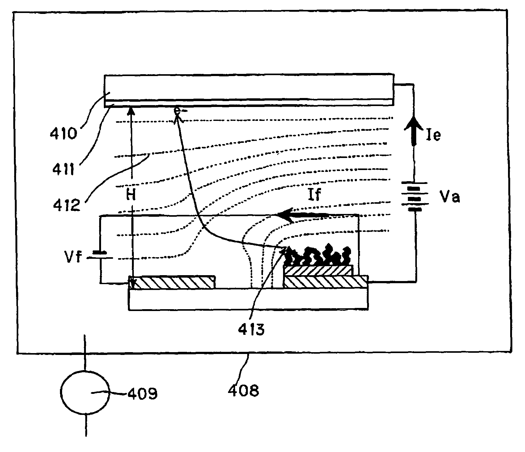
[0129]Next, the above-described substrate was disposed on a uniformly heated region inside a reaction vessel 505 is shown in FIG. 4. Next, the reaction vessel 505 is evacuated until a pressure of 10−6×1.333×102 Pa is reached, by applying a turbo-molecular pump 507 and a rotary pump 508.

[0130]As described earlier, a cylinder 502 stores compressed hydrogen gas diluted with nitrogen gas into 2 vol % of concentration. In the following step, the diluted hydrogen gas was fed from the cylinder 502 into the reaction vessel 505 via a gas flow meter 504 at room temperature and at a flow rate of 0.17 liter per minute. At the same time, ethylene gas diluted with nitrogen gas into 1 vol % of concentratio...

reference examples 1 – 3

Reference Examples 1–3

[0143]In the same way as in Example 1, a substrate was prepared for depositing a bundle of graphite nanofibers thereon. Next, the substrate was set inside a reaction vessel, and the interior space of the reaction vessel was evacuated.

[0144]As in Example 1, an alloy material comprising 90 parts of cobalt and 10 parts of palladium was used as catalytic metal.

[0145]Three ways were used for feeding gas into the reaction vessel.

example 2

[0154]In the same way as was done for Example 1, a substrate was prepared for growing a bundle of graphite nanofibers thereon.

[0155]As a catalytic metallic material, an alloy material comprising 50% of cobalt and 50% of palladium was prepared.

[0156]Then, the substrate was disposed inside a reaction vessel, and then the interior portion of the reaction vessel was evacuated.

[0157]Temperature for feeding hydrocarbon gas and hydrogen gas into the reaction vessel is the same as in Example 1.

[0158]By applying the above-described method, a bundle of graphite nanofibers was formed on the substrate. Diameter distribution of the thus formed graphite nanofibers is shown in FIG. 12. FIG. 12 presents an analytical chart indicating diameter distribution of an bundle of graphite nanofibers produced by applying the method of manufacturing the inventive electron emitting device.

[0159]In the case of the diameter distribution shown in FIG. 12, the mean diameter value of the bundle of the graphite nano...


PUM

PropertyMeasurementUnit
diameter distributionaaaaaaaaaa
diameteraaaaaaaaaa

Abstract

There is provided a method of manufacturing an electron emitting device by disposing a substrate with a catalytic metal film inside a reaction vessel; feeding hydrogen gas and hydrocarbon gas simultaneously into the reaction vessel at a temperature close to room temperature; raising the temperature inside the reaction vessel; and producing carbon fibers by keeping the temperature inside the reaction vessel substantially constant.

Description

[0001]This application is a division of U.S. application Ser. No. 10 / 237,677, filed Sep. 10, 2002, now abandoned.BACKGROUND OF THE INVENTION[0002]1. Field of the Invention[0003]The present invention relates to an electron emitting device using carbon fiber, electron source, image display device, method of manufacturing the electron emitting device, method of manufacturing electron source using the electron emitting device, and method of manufacturing image display device.[0004]2. Description of the Related Art[0005]In recent years, a wide variety of researches have been underway on fibrous carbon materials having an individual diameter in order of nanometer. Typically, a carbon nanotube is cited as an example of the fibrous carbon materials (carbon fibers).[0006]The carbon nanotube is referred to as a fullerene having a cylindrical structure of a single layer or several layers of a graphite being wound, which is a new carbon material discovered in 1991 (refer to Nature, 354, (1991) ...

Claims


Application Information

Patent Timeline
Patent Type & Authority Patents(United States)
IPC IPC(8): H01J9/04H01J1/05H01J1/30H01J1/304H01J9/00H01J9/02H01J29/04H01J31/12
CPCB82Y10/00H01J1/304H01J1/3048H01J9/025H01J9/022H01J2329/00H01J2201/30469H01J1/30
Inventor OYAMA, KAZUNARITSUKAMOTO, TAKEO
Owner CANON KK
Learn More