Optical multiplex communication system, optical transmission apparatus, and control method of optical multiplex communication

Inactive Publication Date: 2006-08-15
FUJITSU LTD
View PDF4 Cites 28 Cited by
  • Summary
  • Abstract
  • Description
  • Claims
  • Application Information

AI Technical Summary

Benefits of technology

[0011]Accordingly, it is a general object of the present invention to provide a novel and useful optical multiplex communication system, an optical transmission apparatus, and a control method of optical multiplex communication, in which one or more of the problems described above are eliminated.

Problems solved by technology

However, in a case where the transmission quality information for respective channels is provided from the receiving part to the transmission part, there is a problem.
Because of this, the optical signal levels that are multiplexed may change greatly so that the optical signal levels of other channels are influenced and the whole of the transmission quality may decline.
Because of this, level controls against the optical signal of the respective signals based on the transmission quality occur frequently so that an automatic level control at the optical amplifier becomes unstable and time for convergence becomes long.

Method used


Image

  • Optical multiplex communication system, optical transmission apparatus, and control method of optical multiplex communication
  • Optical multiplex communication system, optical transmission apparatus, and control method of optical multiplex communication
  • Optical multiplex communication system, optical transmission apparatus, and control method of optical multiplex communication

Examples


Embodiment Construction

[0025]A description will now be given, with reference to the drawings, of the present invention.

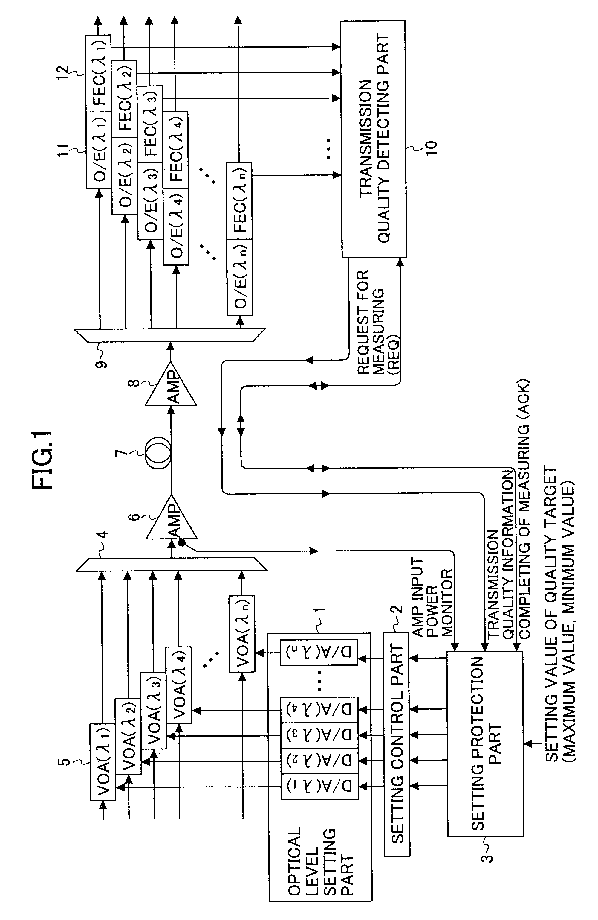
[0026]FIG. 1 is a view for explaining the embodiment of the present invention. An optical level setting part including a DA converter (D / A(λ1)–D / A(λn)) is numbered 1, a setting control part is numbered 2, a setting protection part is numbered 3, an optical multiplexing part is numbered 4, a variable optical attenuation part (VOA(λ1)–VOA(λn)) is numbered 5, an optical amplifier (AMP) is numbered 6, an optical transmission path is numbered 7, an optical amplifier (AMP) is numbered 8, an optical multiplex separation part is numbered 9, a transmission quality detecting part is numbered 10, an opto-electric conversion part (O / E(λ1)–O / E(λn)) is numbered 11, and an error detect correction part for respective channels (FEC(λ1)–FEC(λn)) is numbered 12. The DA converter of the optical level setting part 1, the variable optical attenuation part 5, the opto-electric conversion part 11, and the error ...


PUM


Abstract

An optical multiplex communication system includes a transmission part and a receiving part, wherein the transmission part includes a transmission quality detecting part which measures and transmits a transmission quality information for the channels based on a request from the transmission part; the receiving part includes a variable optical attenuation part controls the optical signal level for the channels, an optical level setting part controls the variable optical attenuation part based on a setting value, a setting control part adding the setting value to the optical level setting part based on a request for setting.

Description

BACKGROUND OF THE INVENTION[0001]1. Field of the Invention[0002]The present invention relates to an optical multiplex communication system and an optical transmission apparatus having a transmission part and a receiving part, and a control method of optical multiplex communication by which multiplexed optical signals are controlled to be transmitted stably.[0003]2. Description of the Related Art[0004]A wavelength division multiplexing (WDM) transmission method is known as a transmission means for transmitting a large amount of information at a high speed. In the WDM transmission method, the optical signals having different wavelengths are respectively assigned to a plurality of channels, so that the optical signals are multiplexed and transmitted to one optical transmission path. In this case, at a transmission part, the optical signals having different wavelengths are multiplexed, amplified by an optical amplifier such as an Er doped optical fiber, and then transmitted to the optic...

Claims


Application Information

Patent Timeline
IPC IPC(8): H04B10/00H04B10/293H04B10/077H04B10/079H04B10/296H04B10/564H04B10/572H04J14/00H04J14/02
CPCH04J14/0221H04J14/02216
Inventor FUNAMI, YOSHIHISAWADA, TETSUOTAKAIWA, KAZUMAROKYOUNO, TOSHIHISATATENO, YASUSHISHIBAYAMA, YOSHIAKINISHIIE, AKINORI
Owner FUJITSU LTD
Why Eureka
Try Eureka