
Dynamic pixel resolution, brightness and contrast for displays using spatial elements

a dynamic pixel and spatial element technology, applied in the field of display, can solve the problems of limiting the resolution and picture sharpness, prone to large amounts of rejects, and high cost of integration of a large number of thin film transistors (tft) to achieve the effect of improving resolution

Inactive Publication Date: 2006-08-15
VP ASSETAB
View PDF4 Cites 35 Cited by
  • Summary
  • Abstract
  • Description
  • Claims
  • Application Information

AI Technical Summary

Benefits of technology

"The present invention provides a display with higher optical resolution for a given grid by dynamically generating pixels from existing dots. The dynamic pixels are generated at a rate high enough not to be perceivable by the human eye. The dynamic pixels consist of at least as many dots that it comprises all the basic colors given by those dots. The dots are chosen so that adjacent pixels overlap partly only, resulting in another dynamic pixel between existing, normally static pixels. The pixels are combined in a manner such as to comprise all basic colors provided by the dots. The dynamic quad pixels comprising common red, green, and blue dots overlap each other on a lower resolution screen to give a perception of the higher resolution display. To compensate the shifting of colors due to the different decreases in light intensity over the time, an automatic or manual colors re-calibrating method is necessary."

Problems solved by technology

One drawback of this kind of display is that the number of pixels is limited by the fixed grid, which limits the resolution and the picture sharpness as well.
The fineness of the grid itself is limited by manufacturing technology, however, because the cathode ray tubes that are used for the displays comprise so-called shadow masks having holes therein which cannot be reduced to whatever size unless one puts up with considerable expenditures.
Likewise, in LCD displays, the integration of a great number of thin film transistors (TFT) is extremely expensive and very prone to produce major amounts of rejects.
In Plasma (PDP) or in FED displays, the technical and economical manufactured size of a RGB pixel is physically limited by the mass production technology itself and further reduction of the RGB pixel size for higher resolution cannot be achieved without huge manufacturing equipment cost and over proportional scraps which are economically not viable.
In LED displays, the placement of the LEDs is complicated and expensive as their space demand is predetermined by their shape.

Method used


Image

  • Dynamic pixel resolution, brightness and contrast for displays using spatial elements
  • Dynamic pixel resolution, brightness and contrast for displays using spatial elements
  • Dynamic pixel resolution, brightness and contrast for displays using spatial elements

Examples


Embodiment Construction

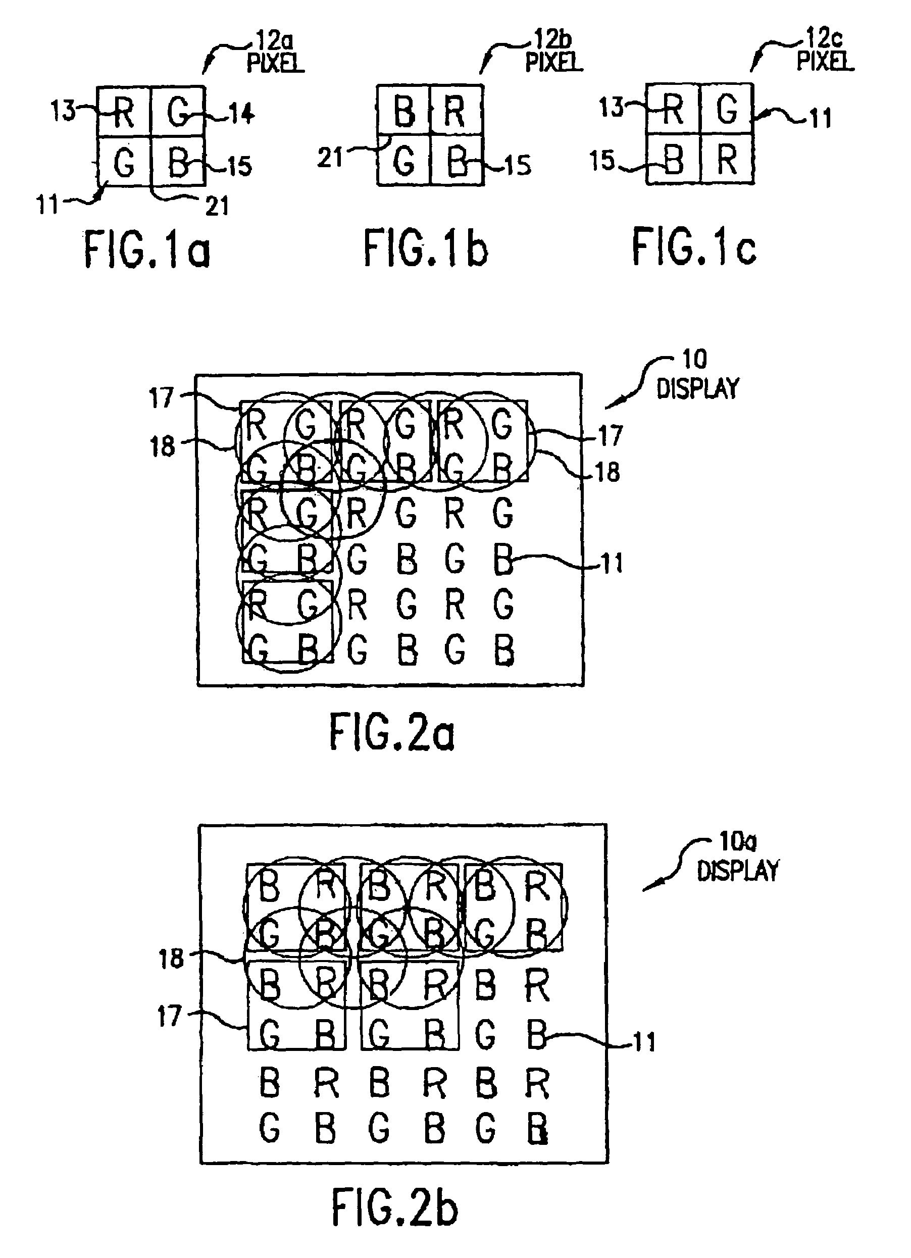
[0046]As shown in FIGS. 1a to 1c, pixels 12a, 12b and 12c have a square shape. Pixels 12a, 12b and 12c comprise regularly disposed dots 11 radiating the basic colours red (red dot 13), green (green dot 14) and blue (blue dot 15).

[0047]In FIGS. 1b and 1c, we observe different dots arrangement in a quad pixel. Preferably, each dot 11 is surrounded by a black mask or black barrier ribs 21 to obtain a higher contrast between the dynamic pixels 18. The precise arrangement of the various colour dots 13, 14, 15 is not critical; care should be taken, however, that the arrangement of the different dots 13, 14, and 15 should be identical in each static pixel 17 within a display 10.

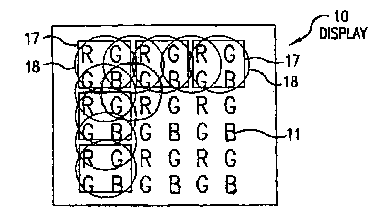
[0048]FIGS. 2a and 2b show displays 10 and 10a having square static pixels 17. Static pixel 17 corresponds to a well known grid pattern or raster of display 10 or 10a. The dynamic pixels 18 shown in a circular form represent the inventive configuration of display 10 or 10a. Each dynamic pixel 18 comprises three dots...


PUM


Abstract

A display including static pixels and dots (individual element) arranged in a predetermined manner. Dynamic pixels are generated dynamically, comprising dots selected from at least two adjacent static pixels. Overlapping of dynamic pixels on the static pixels creates an enhanced resolution at the human's eyes. A weighted dot rendering method can be performed for all static and dynamic pixels of a low resolution inventive display to be displayed in an additive way with the viewing perception of an enhanced higher resolution display. By adjusting the light emitting area and space of dots in a static pixel, maximum optimized brightness in a white balance equilibrium with good contrast can be obtained in finding an optimal ratio between the non light emitting area (black mask or black barrier ribs) and the light emitting area.

Description

CROSS-REFERENCE TO RELATED APPLICATIONS[0001]This is a continuation-in-part of U.S. patent application Ser. No. 10 / 339,491, filed on Jan. 10, 2003; U.S. patent application Ser. No. 09 / 151,287, filed Sep. 11, 1998; and claims priority under 35 U.S.C. §119 and 37 C.F.R. §1.55(a) of German Application No. 197 41 132.0, filed Sep. 13, 1997.BACKGROUND OF THE INVENTION[0002]1. Field of the Invention[0003]The invention relates to a display comprising pixels and dots, including but not limited to the following display technologies: Cathode Ray Tube (CRT), Field Emission Display (FED), Vacuum Florescent Display (VFD), Plasma Display Panel (PDP), Liquid Crystal Display (LCD), Light Emitting Diode (LED), Organic Light Emitting Diode (OLED), Polymer Light Emitting Diode (PLED), Electroluminescence (EL), Electronic inks, Surface Emitting Display (SED), Digital Light Processing (DLP), Electro-mechanics, Phototronics, Biotronics and any light sources known or invented in the future as well as a me...

Claims


Application Information

Patent Timeline
Patent Type & Authority Patents(United States)
IPC IPC(8): G09G5/02G09G3/20G09G3/36H04N9/30
CPCG09G3/2003H04N9/30G09G2300/0452G09G2340/0457G09G2300/0809
Inventor PHAN, GIA CHUONG
Owner VP ASSETAB
Learn More