
Reusable cervical collar having a chin strap member fastening element with a pull cord

Inactive Publication Date: 2006-08-15
SANTELLI JR ALBERT
View PDF33 Cites 47 Cited by
  • Summary
  • Abstract
  • Description
  • Claims
  • Application Information

AI Technical Summary

Benefits of technology

[0008]Summarily described is a cervical collar comprising a collar member, a chin strap member having a first arm attached to the collar member; and a fastening element coupled to a second arm of the chin strap member. The fastening element attaches the second arm of the chin strap member to the collar member at a time of use. The fastening element includes a pull cord member that pulls the fastening element into an aperture in the collar member to attach the second arm of the chin strap member to the collar member at the time of use. The fastening element permits the collar member to be positioned around the neck of a patient from a flat storage position and the chin strap member to be easily positioned and secured minimal movement of the patient.

Problems solved by technology

It is sometimes difficult in an emergency medical situation to insert the fastening element into the aperture in the collar member to secure the free end of the chin support member thereto, after the collar member is positioned around the neck of the patient.
Fastening the chin support member to the collar member before the collar member is positioned around the patient's neck makes the application of the collar member difficult and uncomfortable for the patient, as the patient's head body may need to be moved slightly to fit the collar member around the patient's neck.
Further, present cervical collars are typically discarded after a single use, especially if they become contaminated with blood or other bodily fluids, thus increasing the costs of emergency medical services.
This is because conventional cervical collars must be sterilized in a relatively expensive process, after the blood or other bodily fluid is wiped from the surfaces of the collar.

Method used


Image

  • Reusable cervical collar having a chin strap member fastening element with a pull cord
  • Reusable cervical collar having a chin strap member fastening element with a pull cord
  • Reusable cervical collar having a chin strap member fastening element with a pull cord

Examples


Embodiment Construction

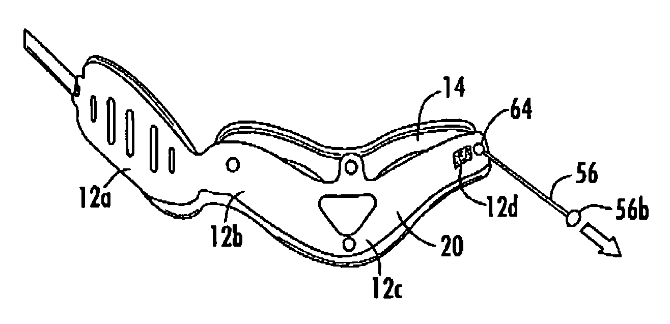
[0019]Referring collectively to FIGS. 1 and 2, there is shown a cervical collar 10 made according to an exemplary embodiment of the present invention. The collar 10 generally comprises an elongated collar member 12, that is capable of being rolled to encircle the neck of a patient, and a chin strap member 14, which supports the chin of the patient.

[0020]The collar member 12 is typically constructed as a unitary, asymmetrical component comprised of a back portion 12a, a first side portion 12b, a front portion 12c, and a second side portion 12d. The free end of the back portion defines a first end 12e of the collar member 12 and the free end of the second side portion 12d defines a second end 12f of the collar member 12. In use, the front portion 12c, which has affixed to it a center portion 14c of the chin strap member 14, is located in the front of the patient's neck under the patient's chin, and the back portion 12a of the collar member 12 is placed behind the back of the patient's...


PUM


Abstract

A cervical collar including a collar member, a chin strap member having a first arm attached to the collar member; and a fastening element coupled to a second arm of the chin strap member. The fastening element attaches the second arm of the chin strap member to the collar member at a time of use. The fastening element includes a pull cord member that pulls the fastening element into an aperture in the collar member to attach the second arm of the chin strap member to the collar member at the time of use. One or more of the components of the collar may be made from materials having an antimicrobial additive which enable the cervical collar to be reused.

Description

RELATED APPLICATIONS[0001]U.S. patent application Ser. No. 10 / 224,939, entitled “FASTENING ELEMENT HAVING A FLEXIBLE PULL CORD”, filed Aug. 21, 2002, now U.S. Pat. No. 6,669,427.FIELD OF THE INVENTION[0002]This invention relates to cervical collars. More specifically, this invention relates to a reusable cervical collar including a fastening element with a pull cord member that facilitates complete assembly of collar at the time of use.BACKGROUND OF THE INVENTION[0003]There are many types of cervical collars that are designed to restrict movement of the head and neck of a person who has suffered a neck or spinal injury. More recent cervical collars are generally constructed from relatively stiff, light-weight plastic materials that are capable of being bent to encircle the neck of the injured patient and yet still provide substantial support for the patient.[0004]Cervical collars commonly include an elongated neck encircling collar member and a strap-like chin support member attache...

Claims


Application Information

Patent Timeline
IPC IPC(8): A61F5/00A61F5/055
CPCA61F5/055Y10S128/23
Inventor SANTELLI, JR., ALBERT
Owner SANTELLI JR ALBERT
Learn More