
Fused loop of filamentous material and apparatus for making same

a filamentous material and loop technology, applied in the direction of soldering apparatus, manufacturing tools,auxillary welding devices, etc., can solve the problems of difficult or impossible control of the suture welding process, failure of suture welds in shear, etc., and achieve the effect of maximizing joint strength

Inactive Publication Date: 2006-08-15
TORNIER INC
View PDF21 Cites 141 Cited by
  • Summary
  • Abstract
  • Description
  • Claims
  • Application Information

AI Technical Summary

Benefits of technology

[0010]The present invention provides a fused loop of an elongated material, such as a polymeric or monofilamentous suture material, which has a strength in-the joint region which is at least equal to, if not greater than, the strength of the parent material. The present invention also provides means for controlling the size and shape of the fused portion of the joint region in order to maximize joint strength.

Problems solved by technology

Because the direct application of heat to sutures in situ may produce undesirable heating of the surrounding tissue, it is preferred to apply non-thermal energy to the suture material in situ to induce localized heating of the suture material in the areas or sections to be fused.
While sutures typically fail under tensile loads applied along the principal axis of the suture, suture welds often fail in shear, i.e., in the plane of the fused region between the overlapped segments of suture material.
Although ultrasonic welding of sutures is known, it has heretofore been difficult or impossible to control the suture welding process in order to produce suture welds of sufficient strength and reliability to replace, or enhance the strength of, suture knots or other loop closure devices.

Method used


Image

  • Fused loop of filamentous material and apparatus for making same
  • Fused loop of filamentous material and apparatus for making same
  • Fused loop of filamentous material and apparatus for making same

Examples


Embodiment Construction

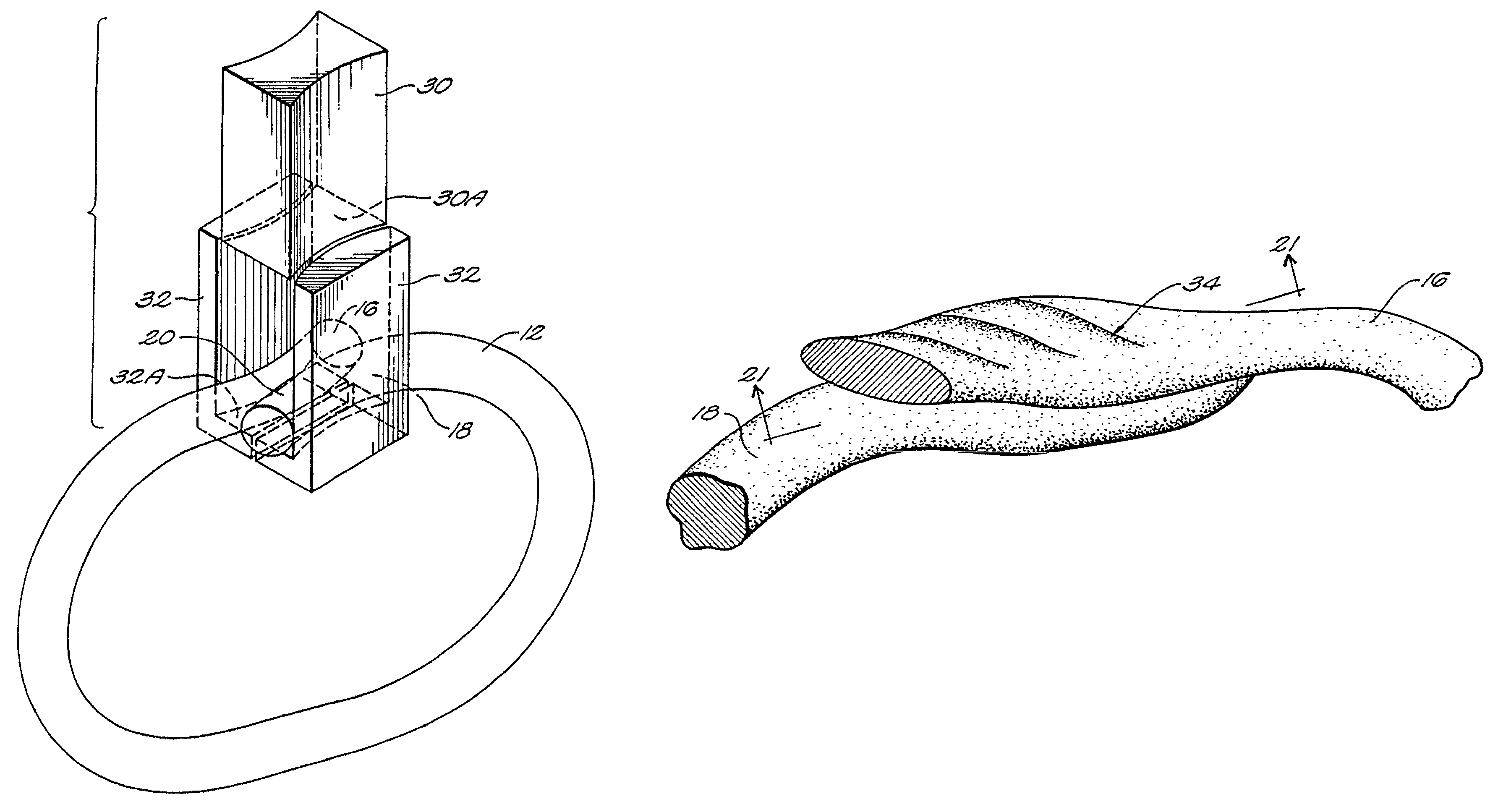
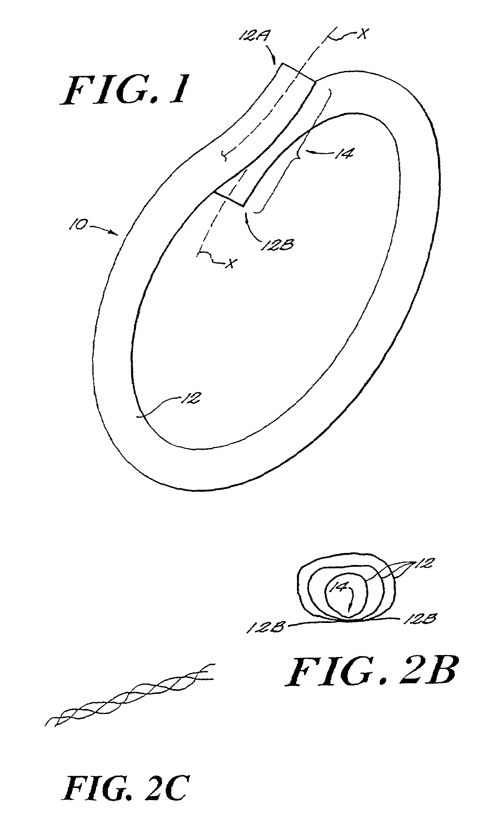
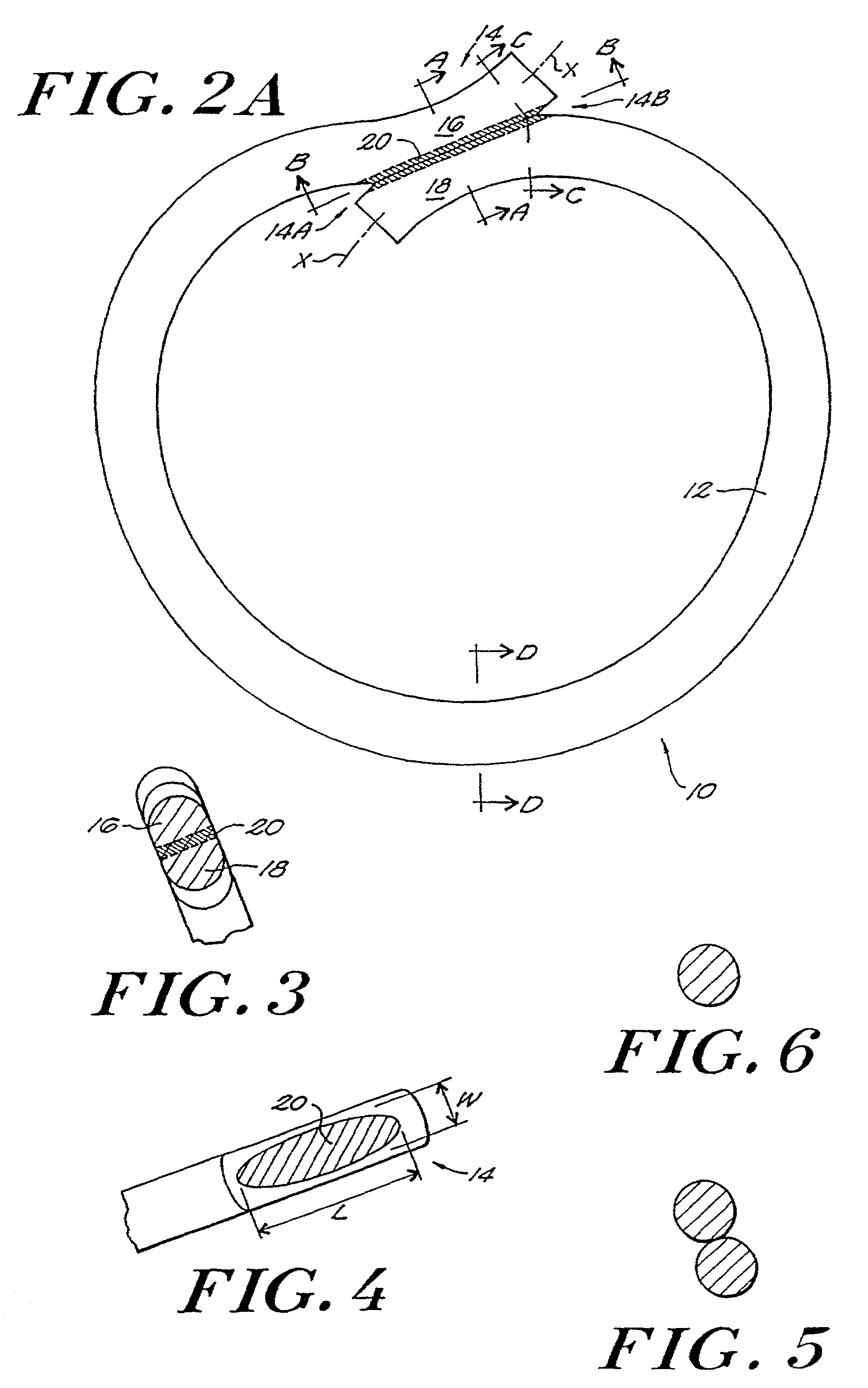
[0057]The present invention provides a fused loop of an elongated material, such as a surgical suture. The loop has at least comparable strength to knotted loops or loops closed by other means by virtue of the properties of the fused portion of the joint region of the loop, as detailed more fully below.

[0058]As shown in FIG. 1, the fused loop 10 of the present invention comprises one or more segments 12 of an elongated material, such as a surgical suture material or other substantially monofilamentous material, which is amenable to bonding through the application of heat or energy thereto. Suitable materials for the elongated material include polymers, especially thermoplastic materials such as, for example, nylon (polyamide), polypropylene, Dacron® (polyester), polyglycolic acid (PGA), polyglyconate, and polydioxanone.

[0059]The fused loop of the present invention is preferably formed through a welding process, in which segments of the material to be joined are locally heated throug...


PUM


Abstract

A welding apparatus that includes a first member having a first suture-contacting surface, a second member having a second suture-contacting surface, and a device for moving the first member relative to the second member to define a gap between the respective suture-contacting surfaces. The first member is capable of vibrating and delivering mechanical energy at ultrasonic frequencies. The second member is stationary relative to the first member. A fixture element is adapted to receive and maintain two or more segments of a material to be welded in a predetermined alignment in the gap between the first and second surfaces of the first and second members during a welding operation. According to another aspect of the invention, an ultrasonic welding apparatus includes first and second members with patterned first and second suture-contacting surfaces. The patterned surfaces can be complementary or non-complementary and the surface patterns on each member may vary in either a periodic or a non-periodic manner.

Description

[0001]This application is a divisional application of Ser. No. 09 / 486,760 filed Dec. 8, 2000, now U.S. Pat. No. 6,358,271; which is a 371 of PCT / US98 / 17770 Aug. 27, 1998; which is a continuation of application Ser. No. 08 / 919,297, filed Aug. 28, 1997, now U.S. Pat. No. 5,893,880, which is a continuation of application Ser. No. 09 / 118,395 filed Jul. 17, 1998, now U.S. Pat. No. 6,286,746.FIELD OF THE INVENTION[0002]The invention relates to improvements in sutures and suturing techniques, and more particularly to materials and devices for making high-strength fused suture loops during surgical procedures.BACKGROUND OF THE INVENTION[0003]In surgical procedures, a monofilamentous suture is typically used to stitch or secure the edges of tissue together to maintain them in proximity until healing is substantially completed. The suture is generally directed through the portions of the tissue to be joined and formed into a single loop or stitch, which is then knotted or otherwise secured in...

Claims


Application Information

Patent Timeline
Patent Type & Authority Patents(United States)
IPC IPC(8): B23K1/06A61B17/08A61B17/04A61B17/00A61B17/06A61B17/32A61L17/00
CPCA61B17/0487B29C66/81433A61L17/00B29C65/08B29C66/69B29C66/80B29C66/81422B29C66/81423A61B17/06166B29C66/8322B29C66/5261A61B17/320068A61B2017/00526A61B2017/0454A61B2017/0619B29C66/81463B29K2023/12B29K2067/043B29K2077/00B29K2101/12B29L2031/709B29L2031/7096B29L2031/7102B29C65/00B29C66/73921B29C66/71B29C66/1122B29K2067/00
Inventor EGAN, THOMAS D.FENTON, JR., PAUL V.
Owner TORNIER INC
Learn More