
Multi-cycle dump valve

a dump valve and multi-cycle technology, applied in the direction of fluid removal, wellbore/well accessories, sealing/packing, etc., can solve the problems of time-consuming and laborious cleaning operation, damage to the zone above the treatment zone, and inoperable wellbore, etc., to achieve the effect of less tim

Inactive Publication Date: 2006-08-15
SCHLUMBERGER TECH CORP
View PDF4 Cites 63 Cited by
  • Summary
  • Abstract
  • Description
  • Claims
  • Application Information

AI Technical Summary

Benefits of technology

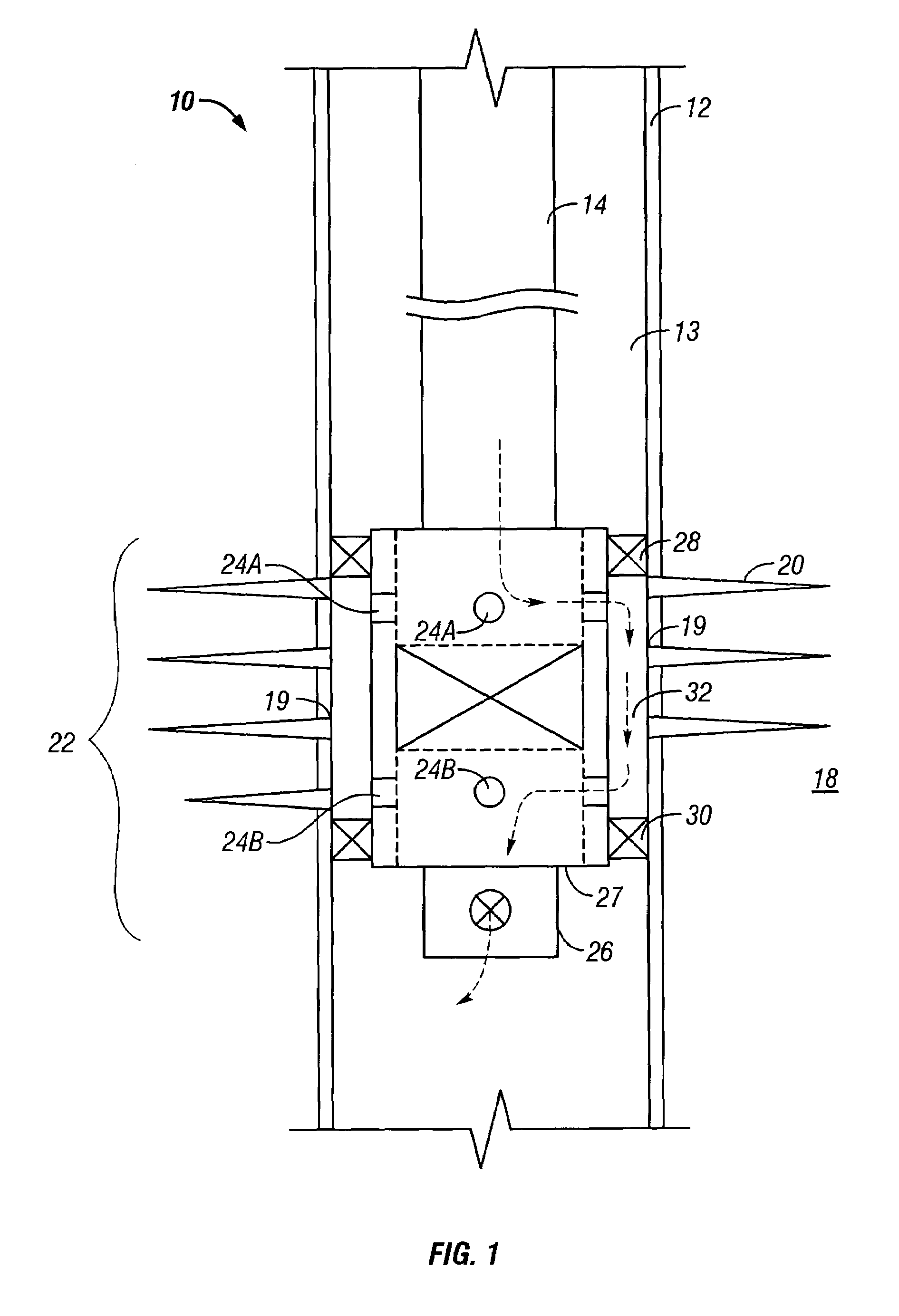
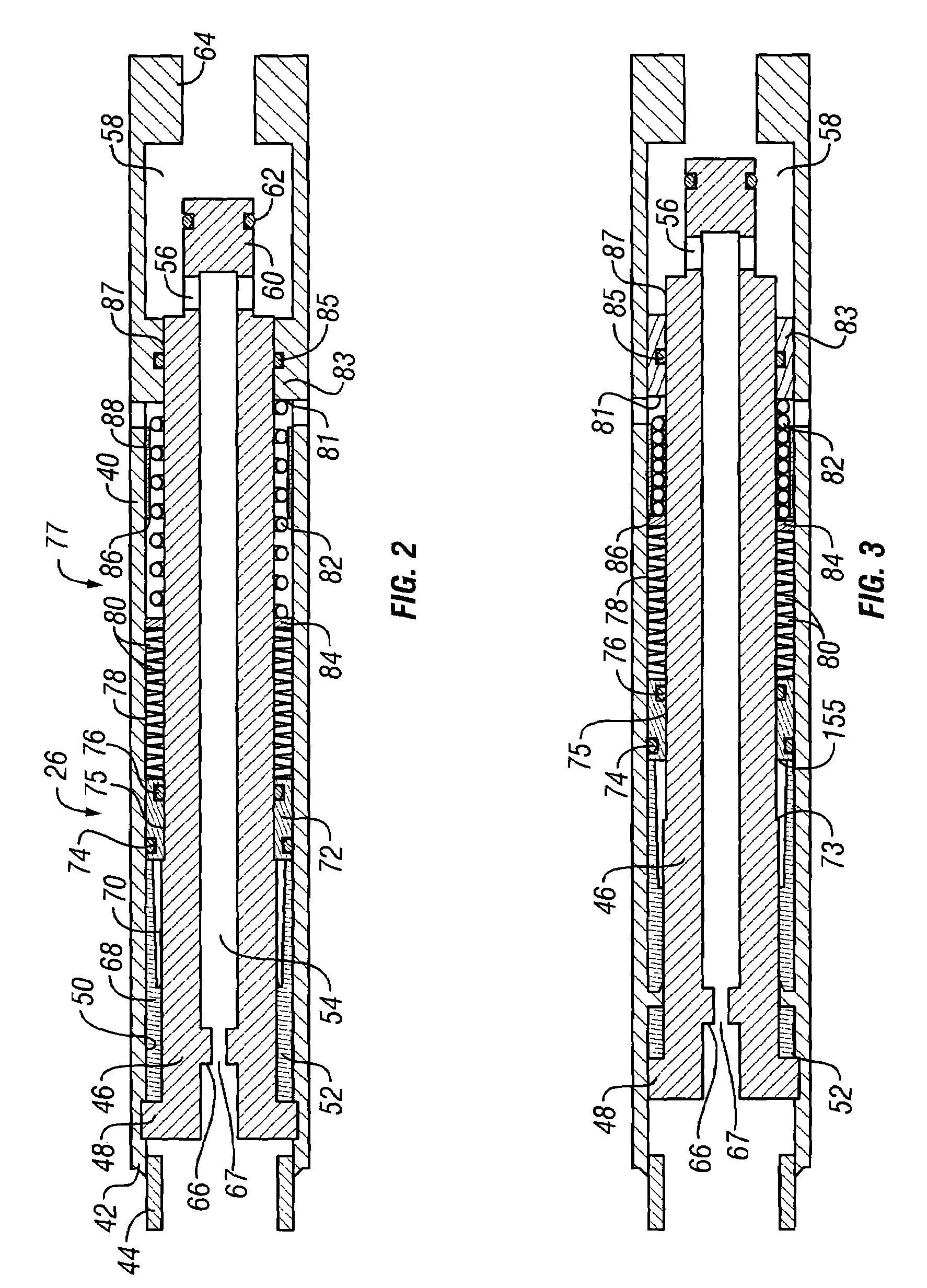
The present invention provides a novel straddle tool with packer elements for sealing within a well casing and isolating a typically perforated casing interval. The tool also includes a dump valve mechanism that is closed responsive to fluid flow of a selected rate to permit treatment of the annulus interval and is opened to its normal position for discharge of fluid from the well below the straddle tool. The tool is conveyed within a wellbore, including highly deviated or horizontal wellbores, on a tubing string composed of coiled-tubing or conventional jointed tubing. The tool is flow actuated, meaning that coiled tubing movement is not required to cycle the device between its operative positions. The tool can be reset with a stored energy source such as a spring, which allows the tool to return to a starting position. The tool is attached below the abrasive slurry delivery device and can be used in wells that can support a full column of fluid. The tool incorporates an operational concept that permits closing the valve against the force of a light spring and using the force of a high force spring to open the valve. The tool uses an indexing system that permits the tool to cycle between an open and a closed condition dependent on the position of the indexing mechanism and differential pressure across the tool.

Problems solved by technology

This clean-up operation is time consuming and is expensive in terms of labor and the time that a wellbore remains inoperable.
More importantly, when pumping down the annulus between coiled tubing and the wellbore, the zones above the treatment zone can be damaged by this clean-out operation.
Further, under-pressured zones above the straddled zone can absorb large quantities of fluids.
Such losses may require large volumes of additional fluid to be kept at surface for the sole purpose of clean-up.
However, this severely limits the application and usage of this tool in demanding well conditions.
However, a high flow rate is needed to close the tool with this large spring.
This proved to be a problem due to many reasons.
Also, this design does not allow operation in wells with bottom-hole pressures below a certain value and fracture gradients below a certain value.

Method used


Image

  • Multi-cycle dump valve
  • Multi-cycle dump valve
  • Multi-cycle dump valve

Examples


Embodiment Construction

[0035]In the following description, numerous details are set forth to provide an understanding of the present invention. However, it will be understood by those skilled in the art that the present invention may be practiced without these details and that numerous variations or modifications from the described embodiments may be possible. For example, although reference is made to a fracturing string in the described embodiments, other types of tubing conveyed downhole well tools may be employed in further embodiments.

[0036]As used here, the terms “up” and “down”; “upward” and downward”; “upstream” and “downstream”; and other like terms indicating relative positions above or below a given point or element are used in this description to more clearly described some embodiments of the invention. However, when applied to equipment and methods for use in wells that are deviated or horizontal, such terms may refer to a left to right, right to left, or other relationship as appropriate. Th...


PUM


Abstract

A flow responsive dump valve mechanism for a straddle packer tool and has a valve controlled flow passage from which underflushed fluid, typically well treatment slurry, in a conveyance and fluid supplying tubing string can be dumped into a well casing. The dump valve mechanism incorporates a ratcheting power piston, an indexing mechanism and high and low load energy storage systems to accomplish open, closed and intermediate dump valve positions. The intermediate position increases the functionality of the tool by preventing accidental closure either due to the free fall of fluid through the coiled tubing or during flushing of the tool and permits the flow rate to be increased for thorough cleaning of the straddle tool and coiled tubing. For energy storage, a light compression spring provides power to cycle the indexing mechanism. Heavier load disc springs (Bellville Washers) are used to provide power for the ratcheting power piston to open the valve.

Description

RELATED INVENTION[0001]The present invention relates to the subject matter of commonly assigned U.S. Patent Publication No. US 202 / 0062963 A1, of David M. Eslinger et. al, published on May 30, 2002, and issued as U.S. Pat. No. 6,533,037 on Mar. 18, 2003, which Publication and Patent are incorporated herein by reference for all purposes. Applicants hereby claim priority in U.S. Provisional Application No. 60 / 422,285, filed on Oct. 30, 2002 by Stephen D. Hill, Robert Bucher, L. Michael McKee, Mark Oettli and Michael Gay and entitled “Dump Valve” and incorporate said Provisional Application by reference herein for all purposes.BACKGROUND OF THE INVENTION[0002]1. Field of the Invention[0003]The present invention relates generally to straddle tools for use in wellbores for stimulation or fracturing of packer isolated annulus intervals and more particularly to straddle tools having valves that are actuated to cause dumping into the well below the straddle tool fluids from a conveyance and...

Claims


Application Information

Patent Timeline
Patent Type & Authority Patents(United States)
IPC IPC(8): E21B34/06E21B23/00E21B33/124E21B34/08E21B34/14
CPCE21B23/006E21B33/124E21B34/14E21B34/08E21B34/063E21B43/26
Inventor HILL, STEPHEN D.BUCHER, ROBERTMCKEE, L. MICHAELOETTLI, MARK C.GAY, MICHAEL G.
Owner SCHLUMBERGER TECH CORP
Learn More