
Audio data transmission system between a master module and slave modules by means of a digital communication network

a digital communication network and master module technology, applied in the field of digital communication networks, can solve the problems of data transmission in isochronous manner, inability to enable the use of existing networks, whatever their architecture, and high cost and resource requirements of the system described, and achieve the effect of low transmission latency

Inactive Publication Date: 2006-08-08
DIGIGRAM
View PDF10 Cites 96 Cited by
  • Summary
  • Abstract
  • Description
  • Claims
  • Application Information

AI Technical Summary

Benefits of technology

"The invention is a system for transmitting audio data between a master module and multiple slave modules using a communication network. The system allows for the use of an existing network and ensures synchronous transmission of data with low latency. The master module has a synchronization clock and supplies data frames with synchronization information to the network terminals of the slave modules. The slave modules have clock reconstitution means and recognition means to ensure synchronous transmission of data within the system. The communication network can be an Ethernet type network. The system can be used in a stadium or hotel to transmit audio data to two different rooms. The invention solves the problems of previous audio communication systems that were not able to use existing networks and did not have low latency transmission."

Problems solved by technology

The system described in this document does not enable an existing network, whatever its architecture, to be used.
The system described is moreover costly and requires large resources.
Data transmission is performed in isochronous manner, which is not suitable for all applications in particular in the case where perfect synchronism would be indispensable.
It does not on the other hand enable live retransmission with very precise synchronization.

Method used


Image

  • Audio data transmission system between a master module and slave modules by means of a digital communication network
  • Audio data transmission system between a master module and slave modules by means of a digital communication network
  • Audio data transmission system between a master module and slave modules by means of a digital communication network

Examples


Embodiment Construction

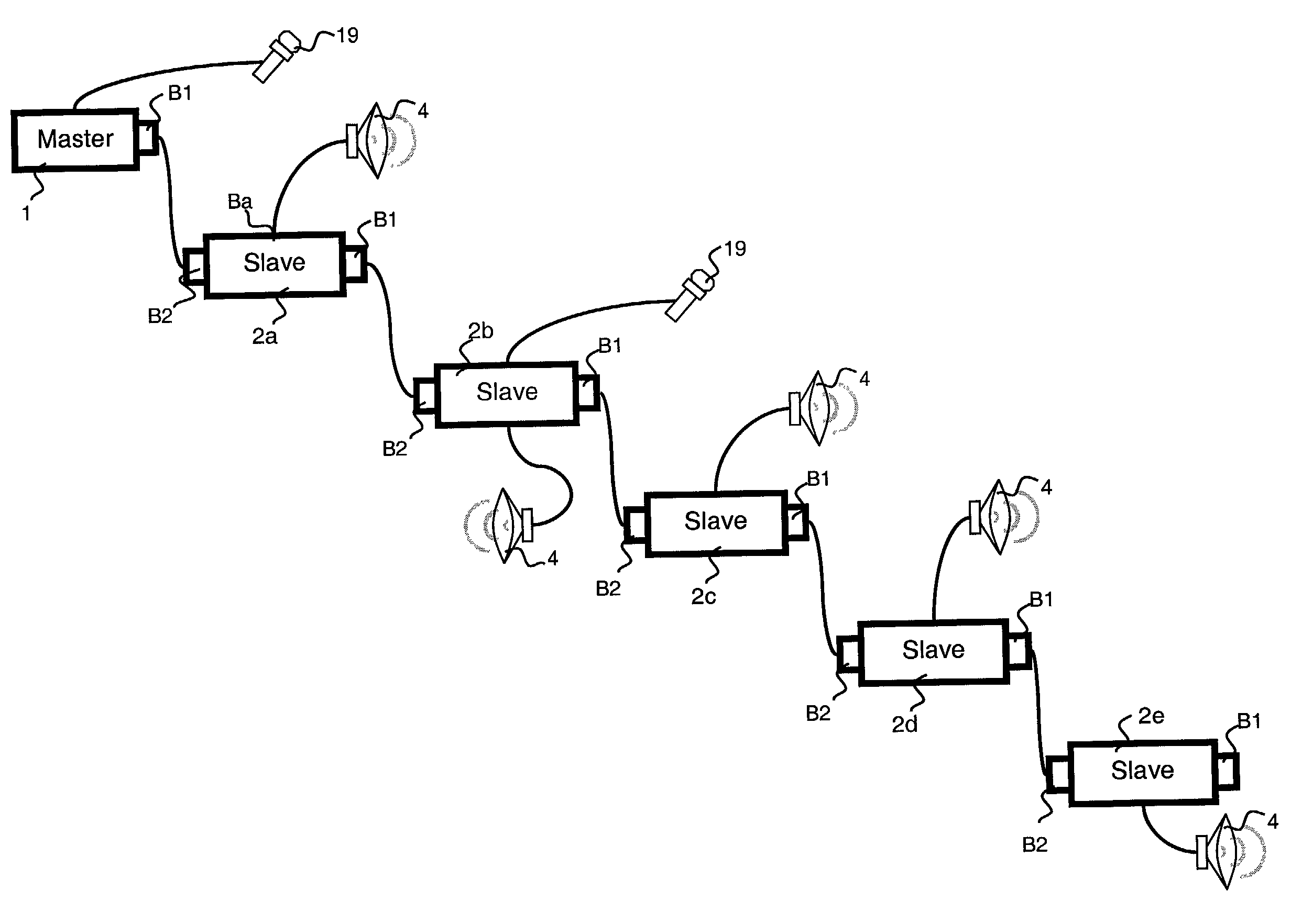
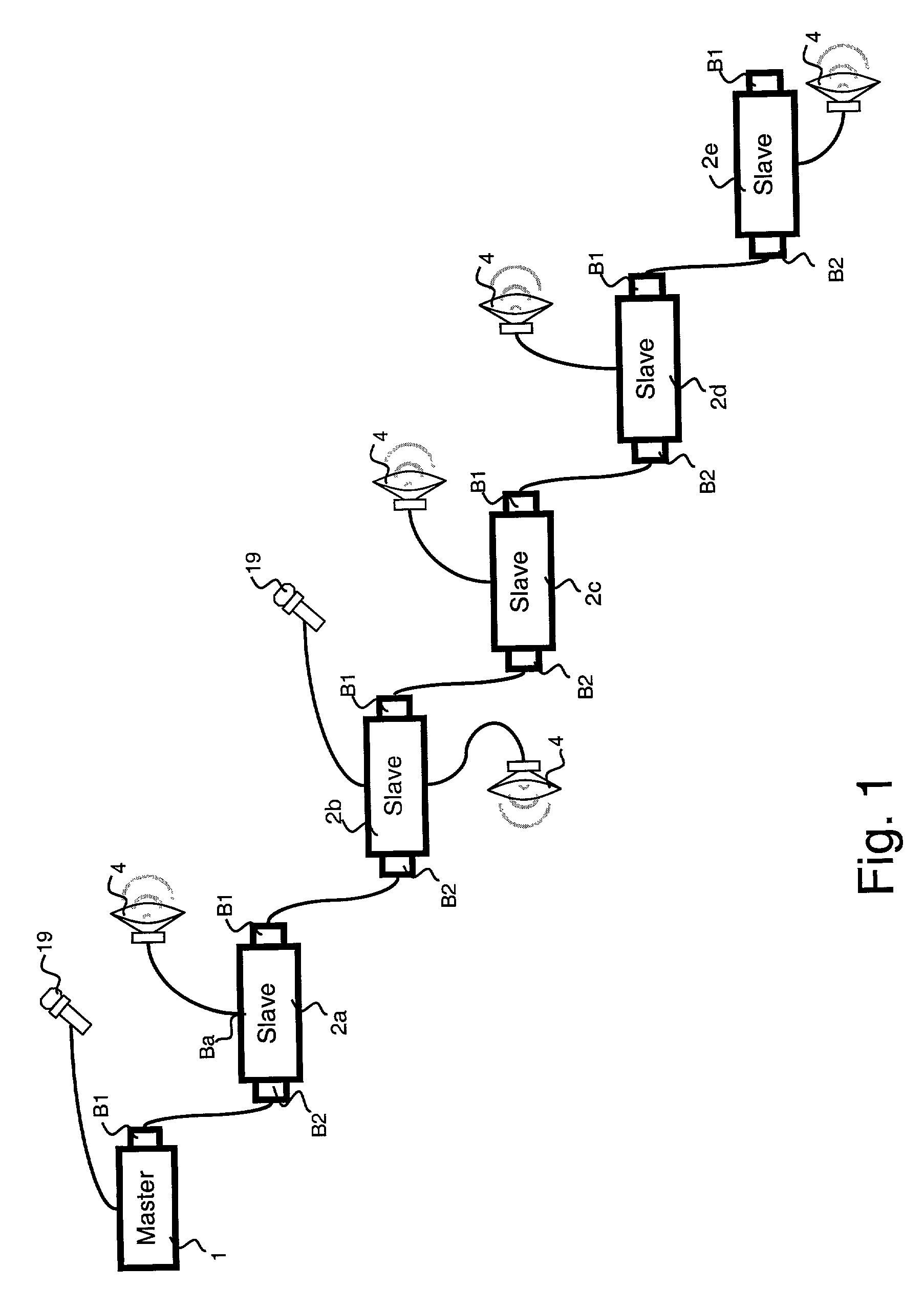
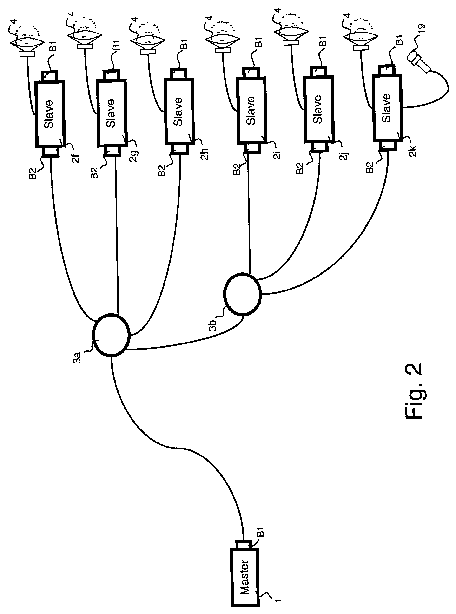
[0019]Whatever its particular configuration, a system according to the invention, as represented in FIGS. 1 to 3, comprises a single master module 1 and a plurality of slave modules 2.

[0020]In FIG. 1, the modules are connected so as to form an open chain. The master module 1 comprises a port constituting a first network terminal B1 connected by means of a two-way communication network preferably of the Ethernet type to a port constituting a second network terminal B2 of a first slave module 2a. The latter comprises another port constituting a first network terminal B1 connected to the second network terminal B2 of a second slave module 2b. In the particular embodiment of FIG. 1, five slave modules 2a to 2e are connected in series, the first network terminal B1 of one of the slave modules being connected to the second network terminal B2 of the next slave module. The first network terminal B1 of the last slave module 2e is not connected to the communication network whereas the second...


PUM


Abstract

The system comprises a master module and slave modules able to be chain-connected and / or star-connected by means of a digital communication network, for example of the Ethernet type. The system is synchronized on the master module clock that supplies synchronization information to all the data frames it sends over the network. Each slave module reconstitutes the clock from the frames it receives. The data frames comprise data packets that can in particular be command data, audio data or video data. Each packet comprises a header describing the content of the packet. Each slave module knows at which location of a packet the data intended for it is located and at which location of a packet it can insert data.

Description

BACKGROUND OF THE INVENTION[0001]The invention relates to a system comprising a digital communication network for data transmission, comprising audio type data, between a master module and a plurality of slave modules, each module comprising at least one network terminal to connect the communication network to the module, at least one network terminal of a slave module being connected to a network terminal of another module by means of the communication network.State of the Art[0002]The document WO-A-0,065,571 discloses an audio communication system enabling digital audio data to be transmitted between a plurality of audio devices via a digital communication network at 100 Megabits / s. This document concerns more particularly a system comprising at least one musical instrument and various electronic components designed for checking and reproducing the sounds generated by this instrument, for example when broadcasting live. The system described in this document does not enable an exis...

Claims


Application Information

Patent Timeline
Patent Type & Authority Patents(United States)
IPC IPC(8): G06F15/16H04L12/44G10H1/00
CPCG10H1/0058H04R27/00H04R2227/003H04R2420/03
Inventor MARINESCU, MARIANANSADE, YVESWEBER, JEREMIE
Owner DIGIGRAM
Learn More