Edge exposing apparatus

a technology of exposing apparatus and exposing surface, which is applied in the direction of photomechanical equipment, instruments, printing, etc., can solve the problems of difficult to assess the performance lowering of light source units, the inability to perform edge exposing operations, and the inability to expose other light source units, etc., to achieve the effect of increasing precision

Active Publication Date: 2006-08-08
SCREEN SEMICON SOLUTIONS CO LTD
View PDF8 Cites 6 Cited by
  • Summary
  • Abstract
  • Description
  • Claims
  • Application Information

AI Technical Summary

Benefits of technology

[0012]This invention has been made having regard to the state of the art noted above, and its object is to provide an edge exposing apparatus capable of (I) avoiding a lowering in the quality of substrates by edge exposure while reducing delays in the edge exposure, and (II) performing uniform edge exposure without influences of a configuration of strands of optical fibers bundled to form a light guide device.

Problems solved by technology

Such an apparatus has only one light source unit, and cannot perform an edge exposing operation in time of changing a lamp in the light source.
It is difficult to assess a lowering of performance of a light source unit, which points to a necessity to change the lamp.
In practice, the lamp is changed only after the performance of the light source unit lowers to the extent of causing trouble in edge exposure.
Consequently, while the necessity is felt for a change, the other light source unit also may lower in performance so that the apparatus is unable to effect edge exposure.
When, after changing the lamp, edge exposure is performed using the new, changed light source unit, light may be emitted in an unstable state, resulting in a reduced quality of substrates.
Then, it is time-consuming and troublesome to put the strands of the fibers in order and arrange the slits.

Method used


Image

  • Edge exposing apparatus
  • Edge exposing apparatus
  • Edge exposing apparatus

Examples


first embodiment

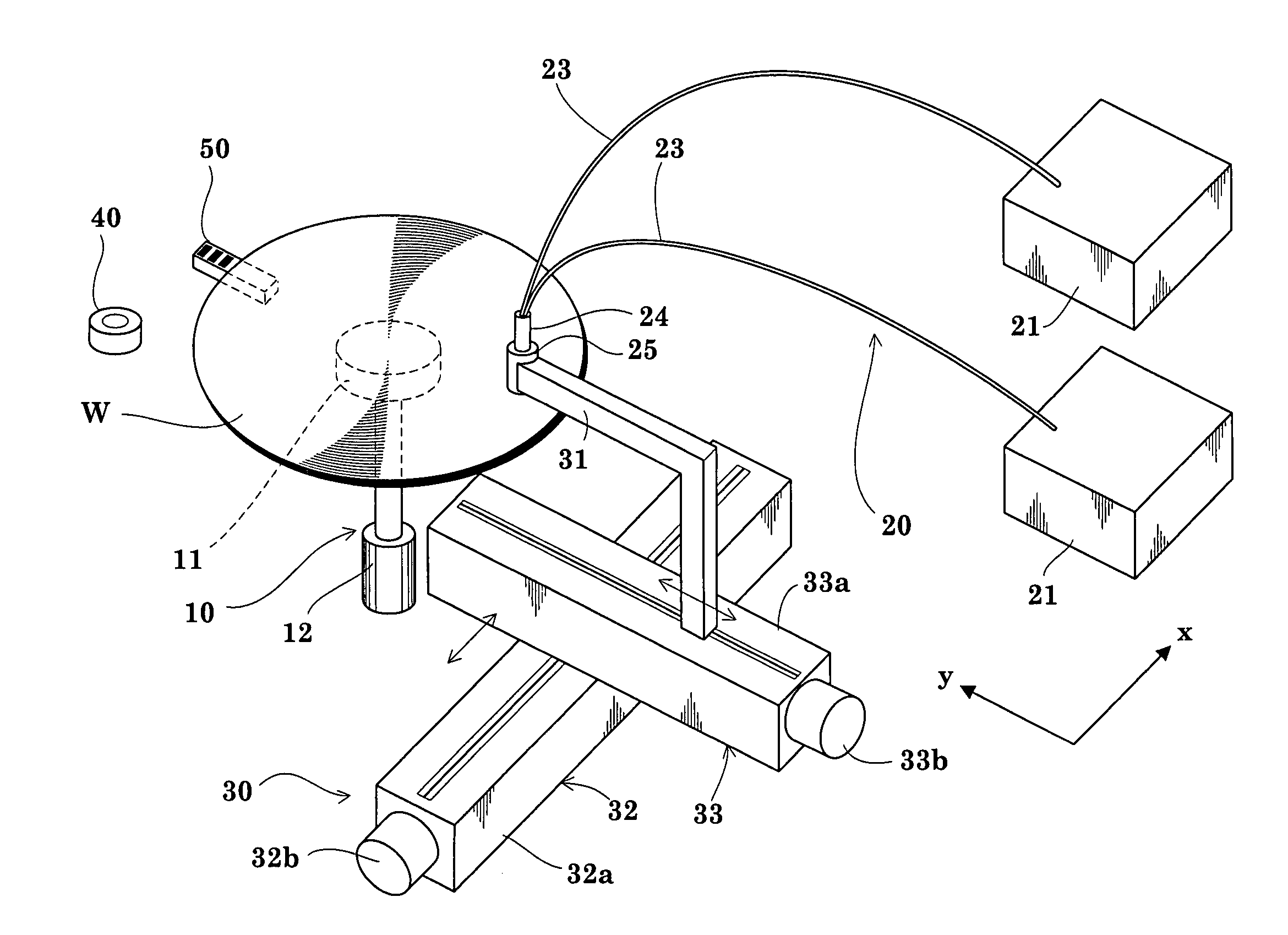
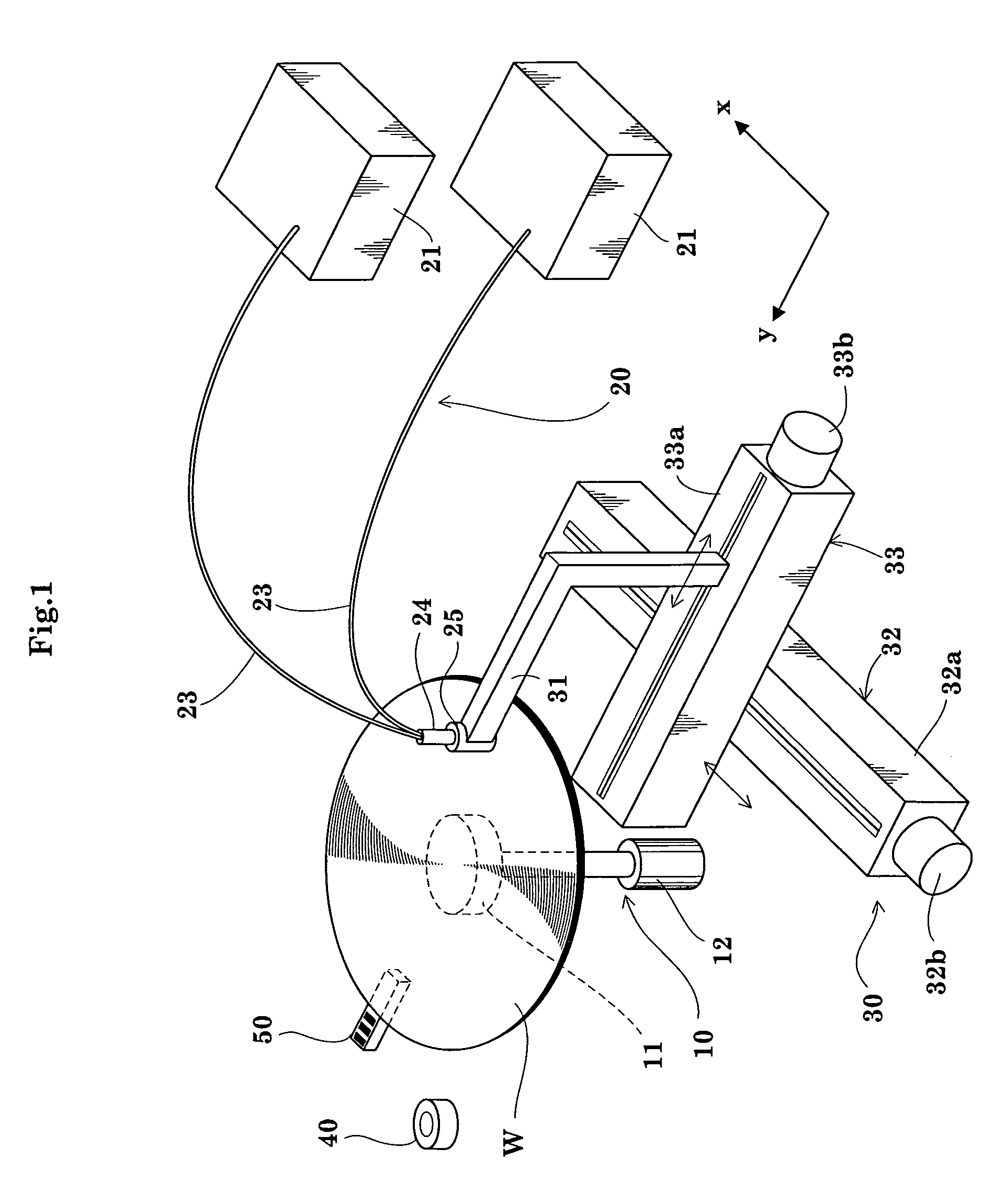
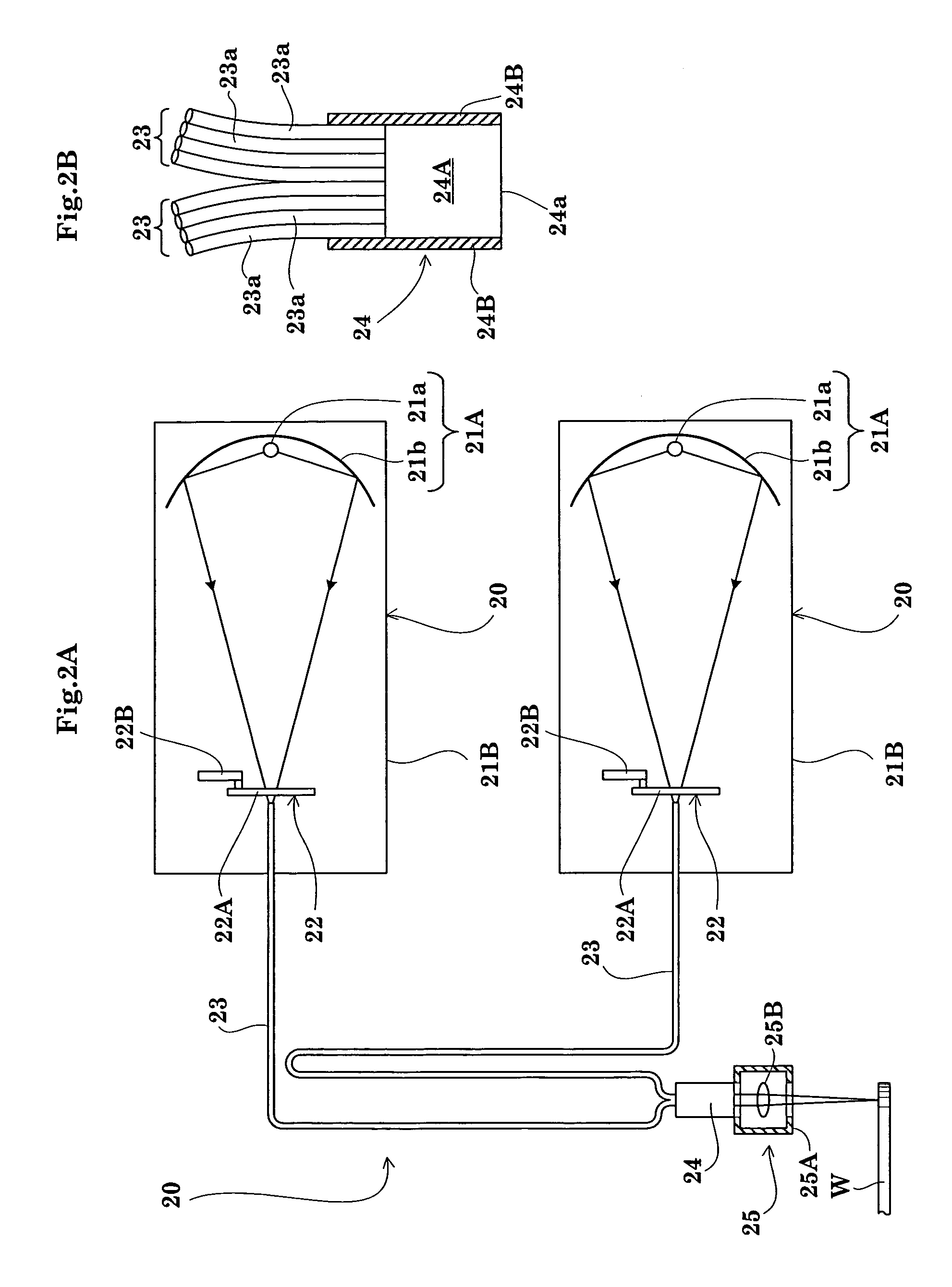
[0074]FIG. 1 is a perspective view showing an outline of an edge exposing apparatus in a first to a third embodiments of the invention. FIG. 2A is a view showing an outline of a treating mechanism. FIG. 2B is an enlarged view of a quartz rod and adjacent components shown in FIG. 2A. FIG. 3 is a block diagram of a control system.

[0075]As shown in FIG. 1, the apparatus in the first embodiment includes a substrate spinning mechanism 10 having a spin chuck 11, a treating mechanism 20 having light source units 21, light guides 23 and an irradiation head 25, and a moving mechanism 30 for moving the irradiation head 25 in a horizontal plane (xy plane).

[0076]The substrate spinning mechanism 10 includes the spin chuck 11 and a spin motor 12. The spin chuck 11 supports a wafer W in horizontal posture by suction. The spin chuck 11 is connected to the spin motor 12 to be rotatable about a vertical axis to spin the wafer W as suction-supported about the vertical axis, i.e. in a horizontal plane....

second embodiment

[0115]The second embodiment of this invention will be described next with reference to the drawings.

[0116]FIGS. 6 and 7 are flow charts of an edge exposing operation in the second embodiment. FIGS. 8 and 9 are timing charts of the edge exposing operation in the second embodiment. The apparatus in the second embodiment has the same construction as in the first embodiment, and will not be described again.

[0117]In the second embodiment, an edge exposing process from start of edge exposure to switch-off is carried out with the two light source units 21. As in the first embodiment, one of the two light source units 21 will be referred to as “light source unit 211”, and the other as “light source unit 212”. In the second embodiment, and in the third embodiment described hereinafter, the lights emitted from the light source units 211 and 212 are mixed by the light mixing optical element 24A. The mixed light is used to irradiate the edge regions of wafer W to perform edge exposure. In the s...

third embodiment

[0155]The third embodiment of this invention will be described next with reference to the drawings.

[0156]FIGS. 10 and 11 are flow charts of an edge exposing operation in the third embodiment. FIG. 12 is a timing chart of the edge exposing operation in the third embodiment. The apparatus in the third embodiment has the same construction as in the first and second embodiments, and will not be described again.

[0157]In the third embodiment, as in the second embodiment, an edge exposing process from start of edge exposure to switch-off is carried out with the two light source units 21. The third embodiment is useful where one of the two light source units is identified as distinguished from the other.

[0158](Step U1) has the Lighting Time of the Light Source Units Reached a Preset Value?

[0159]While an edge exposing operation with the two light source units 211 and 212 is in progress, the lighting time measuring circuit 63 measures a lighting time (irradiation time) from a start of lightin...


PUM

PropertyMeasurementUnit
timeaaaaaaaaaa
lighting timeaaaaaaaaaa
timeaaaaaaaaaa

Abstract

An edge exposing apparatus includes a photo detector and a lighting time measuring circuit for detecting a decrease in performance of light source units. The lighting time measuring circuit detects a ready state ((stabilization of luminous intensity) of the light source units, for example by measuring a lighting time for a startup (switch-on) of the light source units. When the measuring circuit detects a preset lighting time, or when the photo detector detects a luminous intensity below a preset value, the light source units are determined to have lowered performance, and are switched off. When a decrease in performance of one unit is detected, a replacement light source unit is started while continuing edge exposure with one or more other light source unit(s). When a ready state is detected, the edge exposure with the one light source unit is terminated (switch-off), and edge exposure is performed with the replacement light source unit.

Description

BACKGROUND OF THE INVENTION[0001](1) Field of the Invention[0002]This invention relates to edge exposing apparatus for emitting light to and exposing edge regions of substrates such as semiconductor wafers, glass substrates for liquid crystal displays, glass substrates for photomasks, or substrates for optical disks (hereinafter called simply substrates).[0003](2) Description of the Related Art[0004]In a conventional edge exposing apparatus, a light guide in the form of a bundle of optical fibers guides light emitted from a light source unit (light emitting unit) to irradiate and expose edge regions of each substrate. Such an apparatus has only one light source unit, and cannot perform an edge exposing operation in time of changing a lamp in the light source. Japanese Unexamined Patent Publication No. 2002-313708 discloses an apparatus for solving this problem to improve throughput of the edge exposing operation. The apparatus disclosed therein exposes substrate edges by mixing ligh...

Claims


Application Information

Patent Timeline
Patent Type & Authority Patents(United States)
IPC IPC(8): G03B27/42G03B27/54G03F7/20H01L21/027
CPCG03F7/2028
Inventor AKIYAMA, KAZUYAKAMEI, KENJIONO, KAZUYA
Owner SCREEN SEMICON SOLUTIONS CO LTD
Why Eureka
Try Eureka