
Electrospray ionization using pointed fibers

a technology of electrospray and fibers, applied in the direction of isotope separation, electric discharge tubes, particle separator tubes, etc., can solve the problems of reducing the resolution of the separation system on the device, reducing the sensitivity of the electrospray, so as to improve the electrospray efficiency and enhance the sensitivity

Inactive Publication Date: 2006-08-08
MUSC FOUND FOR RES DEV
View PDF8 Cites 10 Cited by
  • Summary
  • Abstract
  • Description
  • Claims
  • Application Information

AI Technical Summary

Benefits of technology

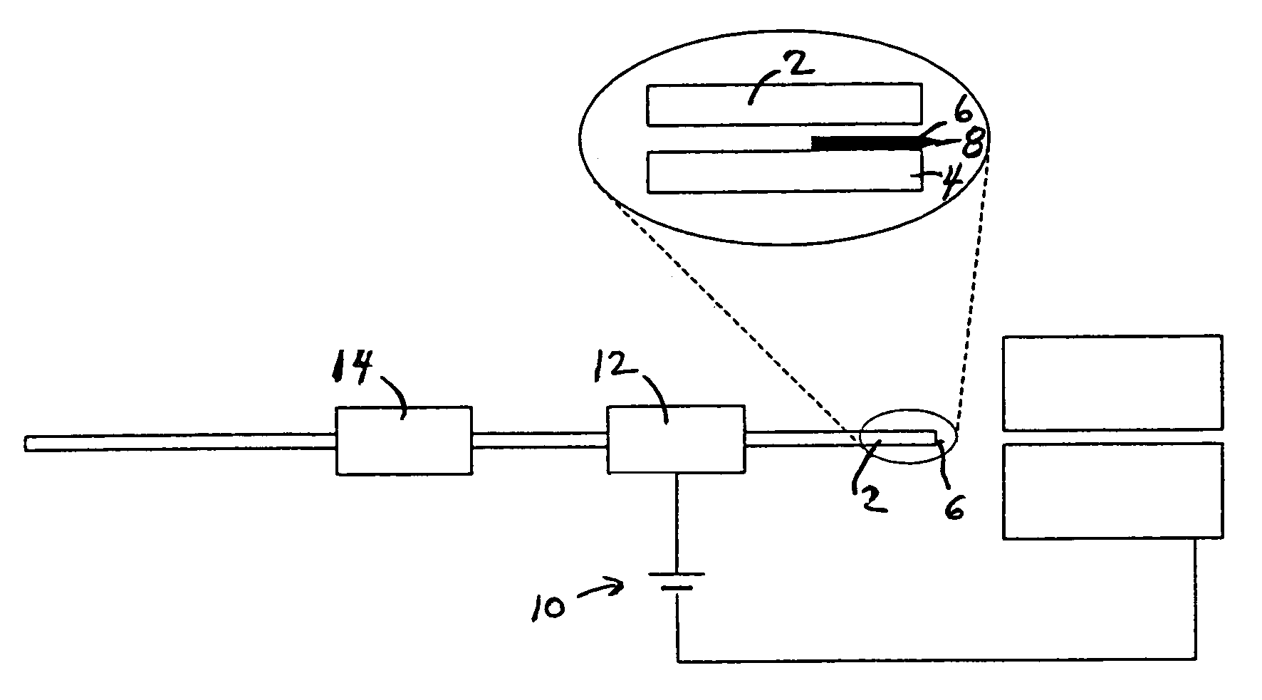
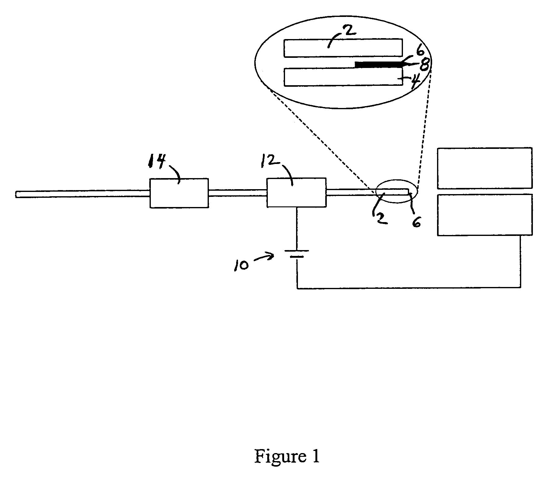
[0008]A pointed carbon fiber electrospray ionization emitter for nanoliquid sampling is presented. A length of electrically conductive fiber is present within a lumen of a microfluidic device. A point is present on an end of the electrically conductive fiber, or the electrically conductive fiber is otherwise sufficiently small on the end to create a desired spray. A conductor supplies electrical current to the electrically conductive fiber. Fluid to be sprayed is transported through the lumen and out of the terminus of the lumen, and an electrical field established by the conductive fiber distributes and sprays the fluid. The conductive fiber produces a small Taylor cone at the tip of the conductive fiber, which generates a stable electrospray. The small Taylor cone improves the electrospray efficiency, thereby enhancing sensitivity. This emitter is rugged, and is able to generate stable electrospray over a wide range of flow rates, voltages; and surface tension variations.

Problems solved by technology

This approach was complicated by the tendency to accumulate a droplet at the exit that formed a mixing volume and degraded the resolution of the separation system on the device.
This approach yields satisfactory electrospray ionization performance, but has two problems: (i) the potential for dead volume in the attachment leading to degradation of separation quality, and (ii) the loss of the key advantage of photolithography-based microfabrication methods, i.e. the ability to make multiples of a function as easily as producing a single function on a device.
These microfabricated electrospray ionization devices gave good electrospray performance, but all of them require relatively complex processes and facilities to produce the devices.

Method used


Image

  • Electrospray ionization using pointed fibers
  • Electrospray ionization using pointed fibers

Examples


Embodiment Construction

[0010]In the embodiment of the invention shown in FIG. 1, an electrospray emitter is constructed from a length of tubing 2. The tubing may be a fused silica capillary. At the emitter terminus 4 of the tubing or capillary, a length of conductive material or conductive fiber 6 is inserted into a lumen of the tubing. The conductive fiber is preferred to be carbon fiber. The carbon fiber may have a diameter of 35 μm or less. The position of the conductive fiber is fixed relative to the tubing. Carbon fiber may be fixed with carbon ink adhesive, or the carbon fiber may be embedded in the tubing. The conductive fiber, such as carbon fiber, protrudes from the tubing terminus. For example, the carbon fiber may extend from the tubing up to 1 mm or more.

[0011]The protruding carbon fiber has a pointed shape on an end 8 that is opposite the tubing. The point may be formed, such as by etching a piece of carbon fiber. The point is formed to be sufficiently “sharp” so that sufficient electrical po...


PUM


Abstract

A pointed carbon fiber electrospray ionization emitter has a length of electrically conductive fiber that is present within a lumen of a microfluidic device, and protrudes from the terminus. A point is present on an end of the electrically conductive fiber, or the electrically conductive fiber is otherwise sufficiently small on the end to create a desired spray. A conductor supplies electrical current to the electrically conductive fiber. Fluid to be sprayed is transported through the lumen and out of the terminus of the lumen, and an electrical field established by the conductive fiber distributes and sprays the fluid. The emitter is rugged and is able to generate stable electrospray over a wide range of flow rates, voltages, and surface tension variations.

Description

[0001]Applicant claims priority from U.S. Provisional Application Ser. No. 60 / 477,105 filed Jun. 7, 2003.[0002]This invention was made with government support under Grant number R21-CA86285, Contract N01-HV-28181 awarded by National Institutes of Health. The government has certain rights in the invention.FIELD OF INVENTION[0003]This invention relates to electrospray devices and processes as used in microfluidic analytical systems.BACKGROUND OF THE INVENTION[0004]Microfluidic analytical systems have been a subject of increasing interest in recent years, particularly for the analysis of biomolecules. Devices have been reported using high performance liquid chromatography, electrophoreses, isoelectric focusing, and electrochromatography separations with photometric, fluorometric, electrochemical, and mass spectrometric (MS) detection methods. Applications of MS detection have been focused upon electrospray ionization (ESI), and several groups have reported the development of microfluid...

Claims


Application Information

Patent Timeline
IPC IPC(8): H01J49/00
CPCH01J49/167
Inventor LIU, JIANKNAPP, DANIEL R.
Owner MUSC FOUND FOR RES DEV
Learn More