Method of separating suspension, in particular for waste water treatment

a technology of suspension and waste water treatment, applied in the direction of sedimentation settling tank, separation process, filtration separation, etc., can solve the problems of failure to fluidize, complex solutions, and tendency to get wors

Inactive Publication Date: 2006-08-08
ECO CHEM RES AGENCY
View PDF30 Cites 7 Cited by
  • Summary
  • Abstract
  • Description
  • Claims
  • Application Information

AI Technical Summary

Benefits of technology

[0027]Considering the effectiveness of removing the thickened suspension, it is beneficial if the separator, and consequently also the separation space, suddenly widens upwards at the place of collecting tubes, while the side of collecting tubes turned to the upper part of shifted inclined outer wall is provided with apertures.
[0028]It is advantageous for the functioning of the apparatus according to the invention that the area of entrance to the separation space makes more than 3 percent and less than 6 percent of the surface of the separation space at the level of withdrawal of liquid without suspension, whereas the area of the separation space immediately under the removal level of thickened suspension makes more than 20 percent, and immediately above the level of thickened suspension removal it makes less than 70 percent of the surface of the separation space at the level of withdrawing liquid without suspension. It is also preferable to maintain a vertical distance of more than one meter between the withdrawal level of thickened suspension and both the height of entry to the separation space and the height of withdrawing the liquid without suspension.
[0031]It is also advantageous if the angle of the upper part of the inclined outer wall is within the range between 52° and 60° or, possibly, if the angle of the inclined inner wall is within the range between 52° and 60°, whereas the angle of the bottom part of the inclined outer wall is within the range of 30° to 40°.
[0032]The most essential advantage of the method and the apparatus according to the present invention is a substantial improvement of the efficiency of separation, which is enabled in particular by the increase of solids load of the separation when separating a concentrated suspension, and namely up to the double achievable by known systems of fluid filtration using a partially fluidized sludge blanket. This can be made use of either for increasing the hydraulic load and, accordingly, for enhancing the separation capacity, or for increasing the concentration of suspension entering the sludge blanket or, possibly, for an optimum combination of both these effects. Such quantitative improvement of separation efficiency will be a special contribution for the activation type of biological waste water treatment regarding the savings in the design of integrated biological reactors. The increase of hydraulic load owing to the application of the method and apparatus according to the present invention allows to cut down the separation space, and namely by up to 50 percent against the dimensions of hitherto known plants using a partially fluidized sludge blanket. This brings not only savings relating to the construction of the separator, but also further construction savings, such as by reducing the necessary height of the integrated biological reactor and easier accommodation of the separator in the reactor. The increased concentration of activated sludge in the biological reactor is also reflected in cutting down the functional volumes that are necessary for biological processes and thereby also cutting down the overall size of the reactor. The reduction of the separator size and the optimisation of the construction and of the dimensions of the reactor allow to achieve considerable savings of material, manufacturing cost, transport, and installation. Another advantage of the method and apparatus for implementing the method according to the present invention is their functioning within a substantially broader range of parameters than in the case of a partially fluidized sludge blanket. This widens the scope of utilisation of the method and the apparatus and enables their substantially improved flexibility during operation.

Problems solved by technology

Due to the fact that the velocity of liquid tends to be slower than the fluidization limit at the surface of the partially fluidized sludge blanket, failures of fluidization are encountered there.
However, also more complex solutions are known, such as in form of inclined feeding channels along the walls of the separation space, or in form of a central inlet pipe passing vertically through the centre of the separation space.
If the throughflow drops under about 50 percent of the rated performance in a fully fluidized sludge blanket used for chemical water treatment, disturbances of fluidization occur that have the tendency to get worse, and within a certain time they result in functional failures.
If the concentration of activated sludge drops under 1–2 kg of dry matter per cubic meter in case of a partially fluidized sludge blanket used for biological treatment of water, a sludge blanket is not established in the separation space, or if the concentration of suspension has dropped under the mentioned limit, the sludge blanket is likely to fall out of the separation space, i.e. it will sink under the separation space.

Method used


Image

  • Method of separating suspension, in particular for waste water treatment
  • Method of separating suspension, in particular for waste water treatment
  • Method of separating suspension, in particular for waste water treatment

Examples


example 1

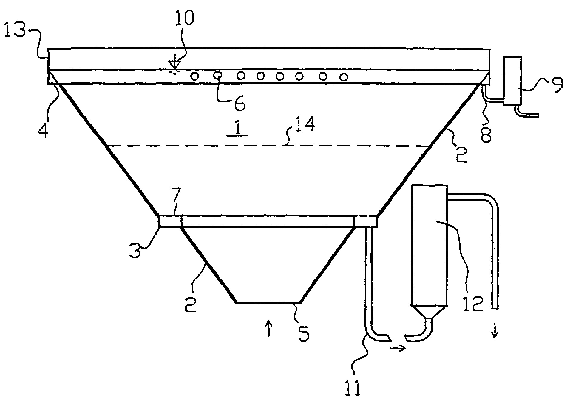
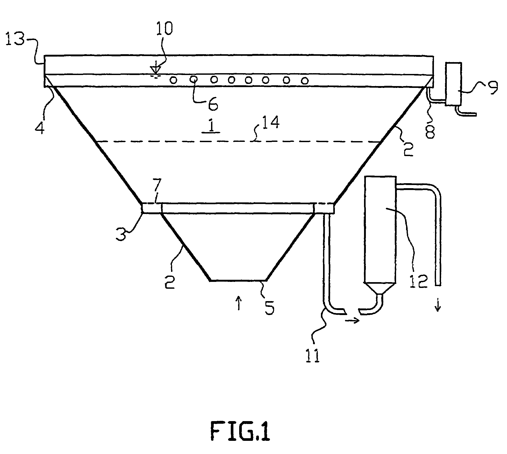
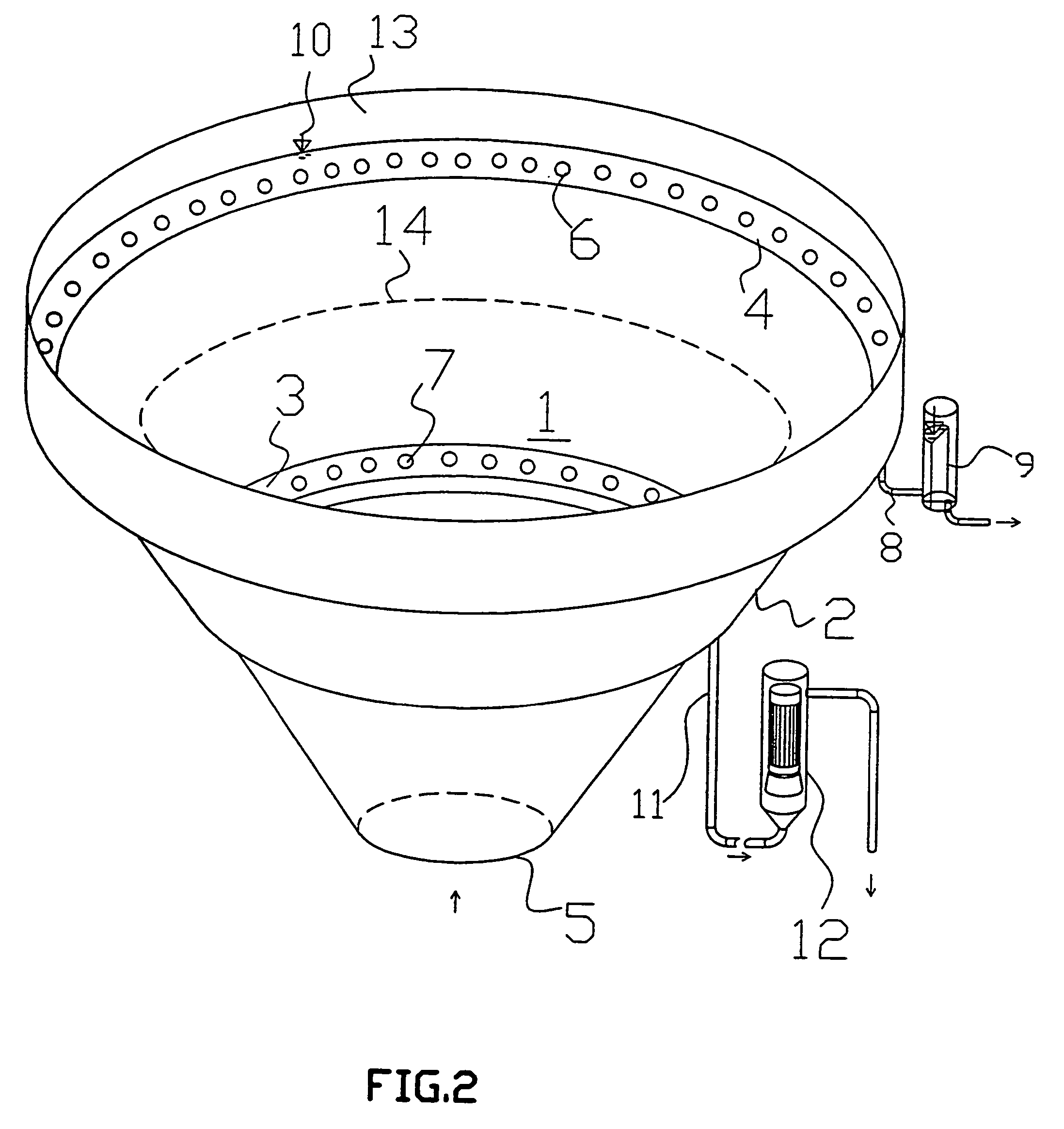
[0044]The basic part of the apparatus for the separation of flocculating suspension according to this invention is separator 1 in form of an upwards widening cone limited by outer wall 2 in shape of a conical casing (FIGS. 1, 2). The shape of the cone of separator 1 can be also non-continuous in the sense that it may comprise not illustrated short cylindrical parts, or even tapered parts of opposite inclination, e.g. due to manufacturing or design reasons.

[0045]The inner space of separator 1 contains a separation space; according to this example of embodiment the inner space of separator 1 practically co-incides with the separation space. The outer wall 2 comprises an inserted means for withdrawing the thickened suspension, and namely in form of a circular wound collecting tube 3 of angular section and its upper part accommodates another means for withdrawing liquid without suspension in form of circular wound collecting tube 4 of triangular section.

[0046]The height of withdrawal le...

example 2

[0128]29 inner wall[0129]30 upper edge of the inner wall[0130]31 thickening space[0131]32 collecting tube

example 3

[0132]33 inclined outer wall[0133]34 inclined outer wall[0134]35 collecting tube[0135]36 collecting tube[0136]37 aperture[0137]38 inlet into separation space[0138]39 rinsing pipes[0139]40 rinsing pipes[0140]41 holes in the rinsing pipe[0141]42 collecting tubes for withdrawing liquid without suspension[0142]43 collecting tubes for withdrawing liquid without suspension[0143]44 inlet pipe for the inlet of pressure air[0144]45 inlet pipe for the inlet of pressure air[0145]46 closing wall[0146]47 passages in the closing wall[0147]48 holes in the collecting tube for withdrawal of liquid without suspension


PUM

PropertyMeasurementUnit
velocityaaaaaaaaaa
water flow velocityaaaaaaaaaa
velocityaaaaaaaaaa

Abstract

A method of separating suspension, in particular for treatment of waste water, wherein the flocculating suspension is separated from the liquid by filtration in a fluidized layer in a sludge blanket wherein the flocks are created from the separated suspension and the fluidization is maintained by the rising stream of liquid, while the liquid with suspension enters the fluidized layer from the bottom and the liquid freed from suspension is discharged above the surface of the sludge blanket represented by the interface between the fluidized layer and the liquid without suspension. The thickened separated suspension in form of flocks from a sludge blanket is withdrawn from the zone of the fluidized layer, the velocity of upward flow in the fluidized layer essentially decreasing in the upward direction. The apparatus for performing this method contains an upward widening separator (1) provided by inlet (5, 38, 59) of treated suspension in its bottom part, and by means for withdrawing the liquid without suspension at its top. A separator (1) the inner space of which contains a separation space is provided with at least one withdrawal spot of the thickened suspension from separation space that is arranged above the inlet (5, 38, 59) into separator (1), predominantly at its outer wall (2) or outer walls (33, 34, 50, 51) and under the surface of the sludge blanket.

Description

FIELD OF THE INVENTION[0001]The invention relates to a method of separating suspension, in particular for treatment of waste water, wherein the flocculating suspension is separated from the liquid by filtration in a fluidized layer in a sludge blanket wherein the flocks are created from the separated suspension and the fluidized state is maintained by the rising stream of liquid, while the liquid with suspension enters the fluidized layer from the bottom and the liquid freed from suspension is discharged above the surface of the sludge blanket represented by the interface between the fluidized layer and the liquid without suspension. Further it relates to an apparatus for performing this method containing an upward widening separator that is provided with the inlet of liquid with suspension in its bottom part, and a means for withdrawal of liquid without suspension in its upper part.DESCRIPTION OF THE PRIOR ART[0002]One of the most advanced methods for the separation of flocculating...

Claims


Application Information

Patent Timeline
Patent Type & Authority Patents(United States)
IPC IPC(8): C02F1/52B01D21/02C01B39/48C02F3/12C02F3/34
CPCC02F1/5281C02F2209/40C02F3/12
Inventor MACKRLE, SVATOPLUKMACKRLE, VLADIMIRDRACKA, OLDRICH
Owner ECO CHEM RES AGENCY
Why Eureka
Try Eureka