
Window or door with protection against explosive effects

Inactive Publication Date: 2006-08-08
SALZER SICHERHEITSTECHN
View PDF8 Cites 23 Cited by
  • Summary
  • Abstract
  • Description
  • Claims
  • Application Information

AI Technical Summary

Benefits of technology

[0012]As a result, the peak load is considerably reduced in any case during the initiation of the force into the ambient brickwork which does not occur at the beginning of the blast wave.
[0014]As a result of this measure, the force to be absorbed by the building parts enclosing the opening is reduced even further because a part of the energy is dissipated beforehand by the interposed damping elements. The higher the displacement of the closure in the direction of the force which occurs during the introduction of the force and the higher the force occurring thereby, the higher the energy absorbed during this process and the lower the force peak that may occur at the end of the displacement path and be absorbed by the building parts.
[0015]An especially advantageous further development is in this connection that the fastening elements are conventional anchors, e.g. screws arranged in dowels, which penetrate the tensile legs in oblong holes extending parallel to the direction of the possible displacement. It is also prevented in this manner that the brackets can escape in a direction parallel to the plane defined by the filling.
[0018]A simple possibility for joining the closure with the brackets is that they are screwed together with a frame element. The screwed connection is especially advantageous because in this case different materials in the frame element (e.g. aluminum) and the brackets (e.g. steel) can be combined with each other.

Problems solved by technology

It has proven to be disadvantageous in connection with the aforementioned connection elements in that they are not suitable for a secure anchoring of closures of buildings in cases where the parts of buildings into which the pertinent bores are introduced do not have the required strength.
This can be the case in old buildings with brittle stone materials or even sandy or at least insufficiently strong casts in the region of the reveal.
Difficulties in connection with the said fastening elements also occur when, as is frequently the case in new buildings, perforated bricks are used in which the air chambers form a relevant part of the stone material.
In the case of higher pressure loads, the conventional fastening of the closures can lead to the consequence that they are pulled completely out of their anchoring.
Moreover, an opening of the known windows is not possible due to the direct damping connection between the laminated safety glass and the Z-like profile.

Method used


Image

  • Window or door with protection against explosive effects
  • Window or door with protection against explosive effects
  • Window or door with protection against explosive effects

Examples


Embodiment Construction

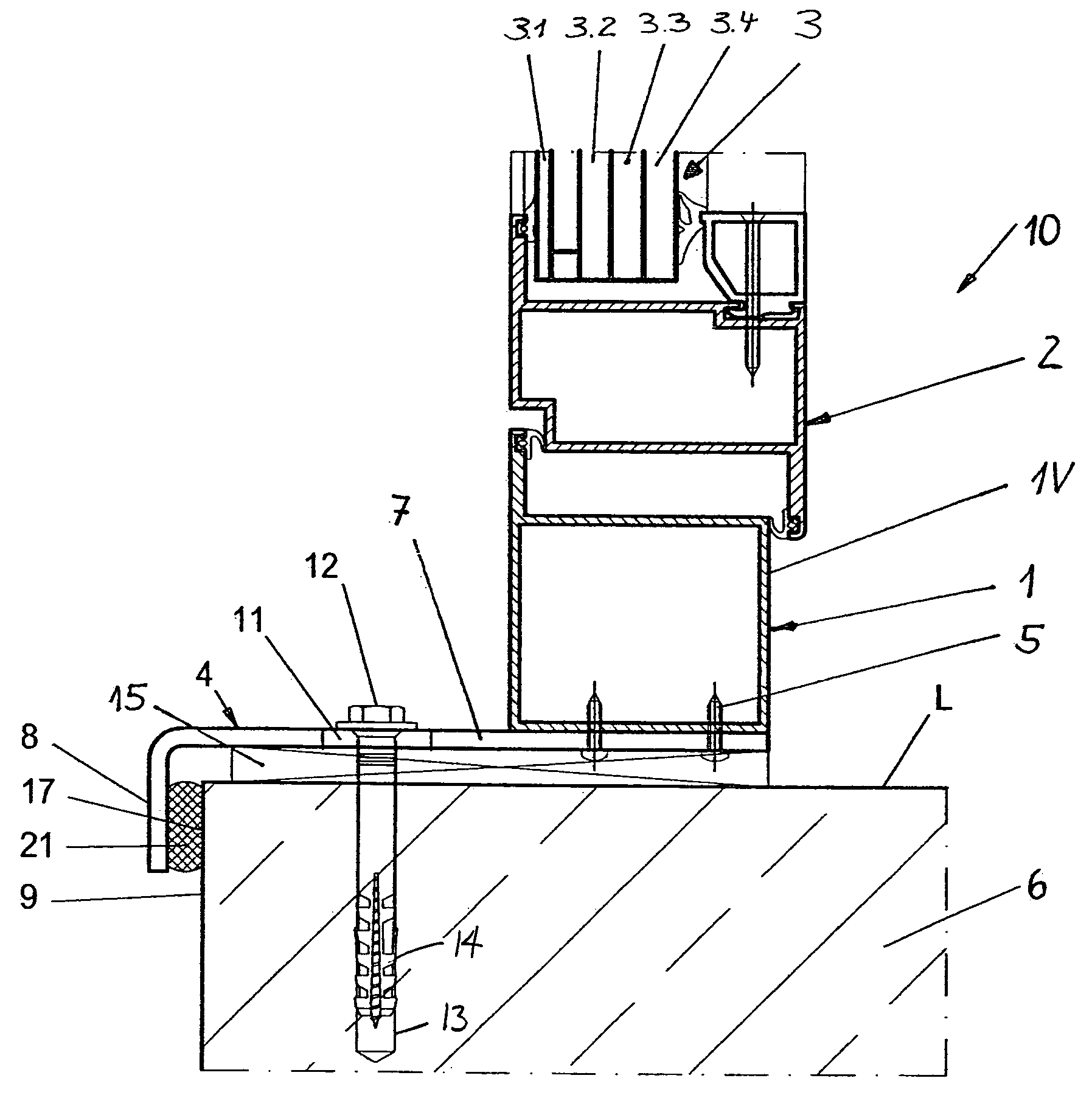
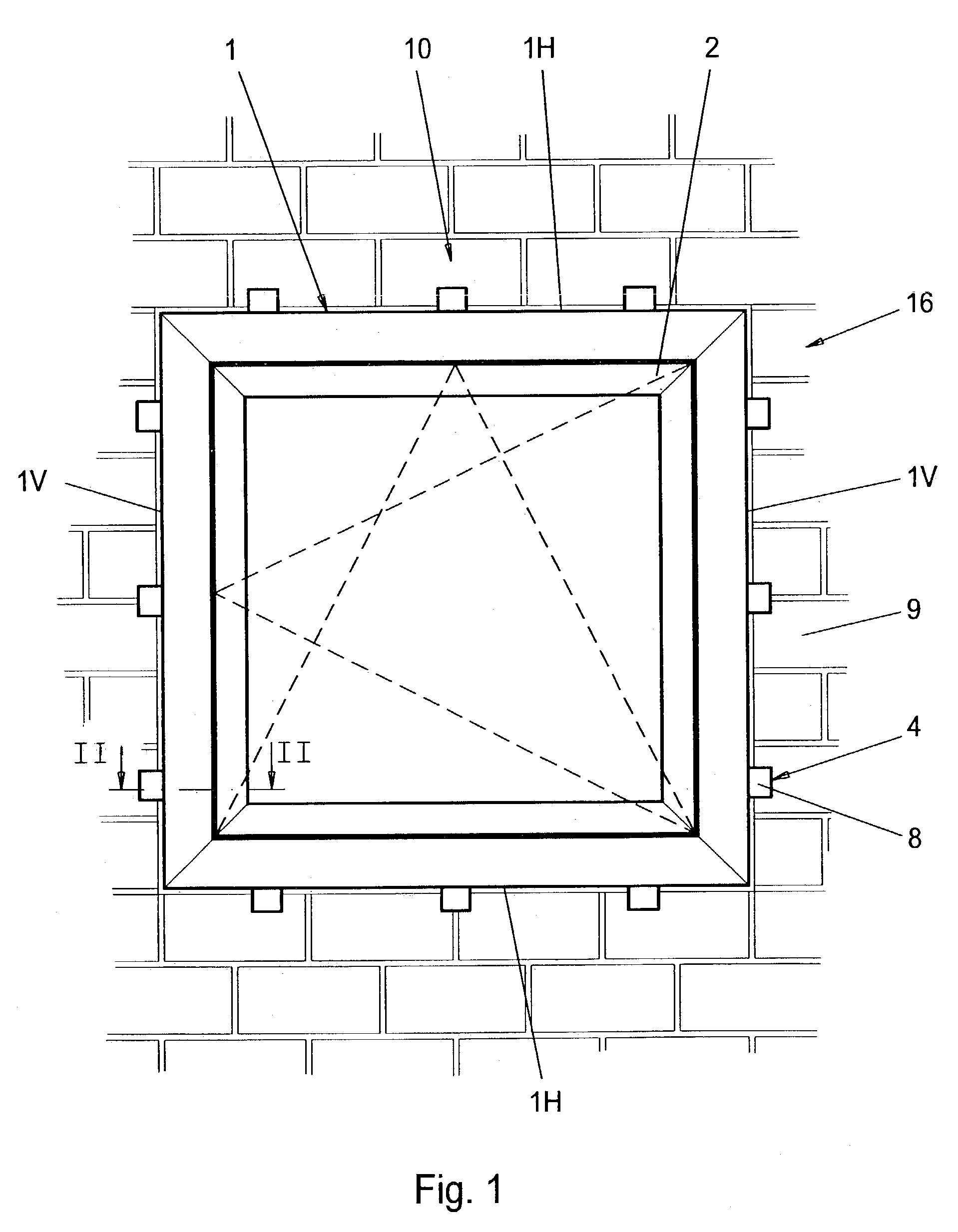
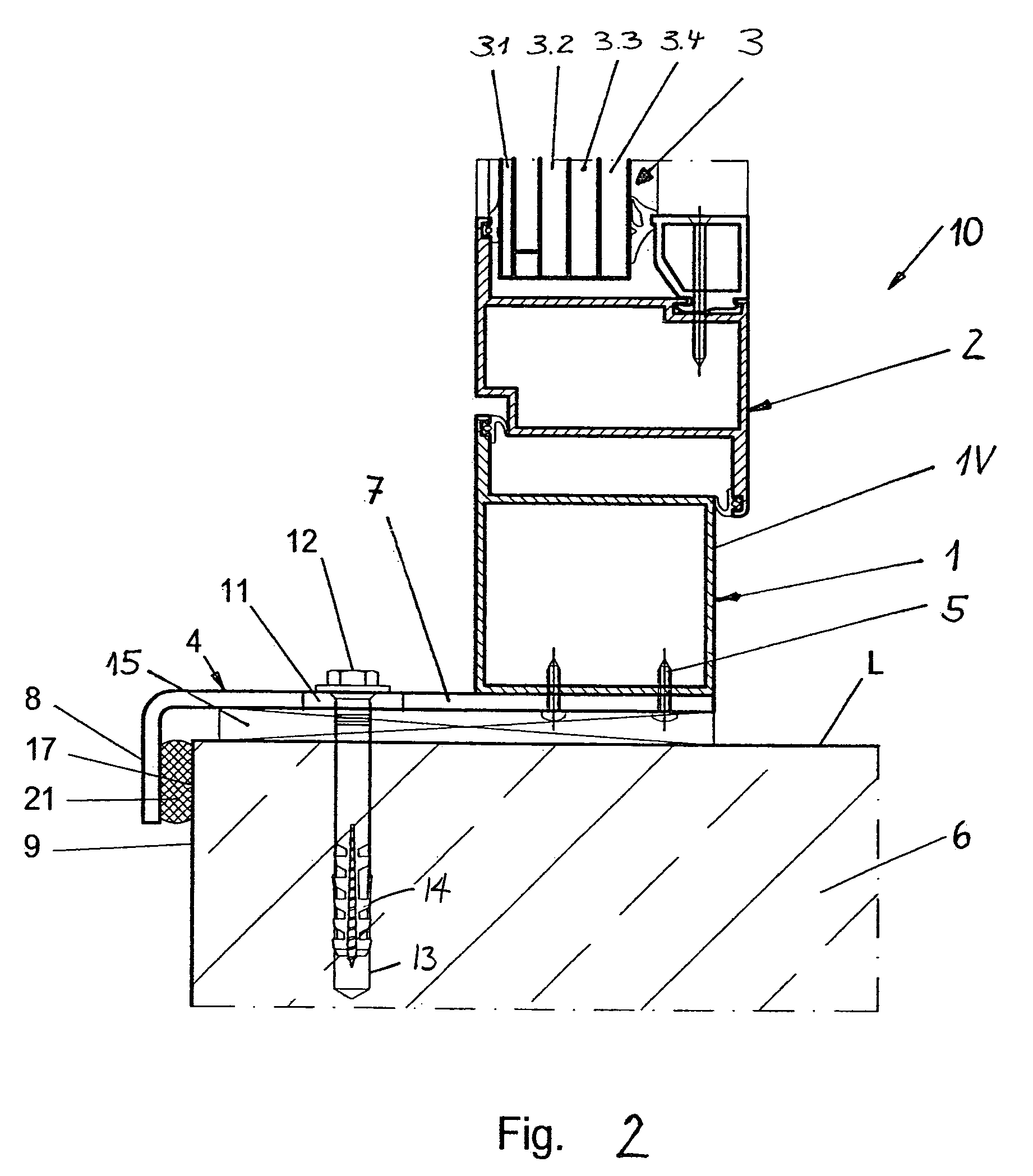
[0028]A closure 10 of a building as shown in FIGS. 1 and 2 consists of a window frame 1 which is composed of two horizontal frame legs 1H and two vertical frame legs 1V as well as a casement 2 which is held therein in a pivoting and tilting fashion and which is composed in the known manner of two opposite horizontal and vertical frame legs each. The casement 2 comprises a filling 3 which consists of four glass panes 3.1, 3.2, 3.3 and 3.4 which extend parallel with respect to each other.

[0029]All four legs 1V and 1H of the window frame 1 are each provided with three brackets 4 which are screwed together by means of two sheet metal screws 5 with the window frame 1 which is arranged as a hollow profile. Every bracket 4 consists of a tensile leg 7 extending parallel to the reveal L of a building part 6 and a supporting leg 8 which is arranged rectangularly with respect to the same and extends at a distance parallel to a visible side 9 of the building part 6. Furthermore, the tensile leg...


PUM


Abstract

A closure (10) for a building which is inhibitive to explosive effects and with which an opening in a building can be closed off comprises a filling (3) as well as frame elements (1, 2) which enclose the same substantially in a circular fashion. Said frame elements (1, 2) are connected in a non-positive way by means of fastening elements with parts (6) of the building which are adjacent to the opening. In order to achieve a secure connection which withstands high loads between the closure (10) and the part (6) of the building made of building materials of low strength, it is proposed rectangular brackets (4) are fastened to the frame elements (1) on at least two opposite sides of the closure (10). At least one tensile leg (7) each of the brackets (4) extends close to the reveal (L) of the opening. At least one supporting leg (8) each of the brackets (4) extends at a distance from the visible side (9) of the part (6) of the building adjacent to the opening.

Description

BACKGROUND OF THE INVENTION[0001]1. Field of the Invention[0002]The invention relates to the closure of a building which is designed in a manner so as to be inhibitive to an explosive effect, with the closure being used to seal off a building and comprising a filling and frame elements substantially circularly enclosing the same, with said frame elements being connectable in a non-positive manner by means of fastening elements with parts of the building adjacent to the opening.[0003]Closures of a building within the terms of the present invention shall especially be understood as being doors or windows. The latter can be provided with rigid as well as rotatable and / or tiltable designs. Principally, it is also possible to consider all other planar elements such as facade elements or the like, irrespective of whether they are designed of metal and / or plastic and / or glass and / or wood, with which the opening of a building can be closed off. The term frame elements shall be defined withi...

Claims


Application Information

Patent Timeline
IPC IPC(8): E04H9/00E06B1/60E06B5/12
CPCE06B1/6015E06B5/12E06B1/6084
Inventor SALZER, HEINRICH
Owner SALZER SICHERHEITSTECHN
Learn More