
Vehicular communication system

a communication system and vehicle technology, applied in the field of vehicle communication systems, can solve the problems of large dynamic range, large transmitters, receivers, etc., and achieve the effect of reducing the load of communication equipmen

Active Publication Date: 2006-08-01
LOCKHEED MARTIN CORP
View PDF189 Cites 33 Cited by
  • Summary
  • Abstract
  • Description
  • Claims
  • Application Information

AI Technical Summary

Benefits of technology

[0005]A communication system according to an aspect of the invention includes a set of electromagnetic / electrical transducers. This set may contain as few as one electromagnetic / electrical transducer. Each of the transducers signals between free space and at least one associated electrical port. The communication system includes a plurality of sources and sinks (including receivers) of optical communications signals. The optical communications signals may be analog or digital, and may include control signals. These control signals include signals for controlling the transmitters and receivers, as by selecting frequency, bandwidth, and / or power.

Problems solved by technology

A major contributor to the weight of modern vehicles is the load of communication equipment, including antennas, transmitters, receivers, controllers, input devices such as microphones and cameras, output devices such as monitors and headphones, and transmission lines interconnecting the various elements of the communications system.
A major problem with use of a full-duplex transceiver with an associated antenna is the large dynamic range necessary to isolate the high-level transmitted signal from the low-level received signal.
The problem of reflections is particularly severe in optical fiber transmission paths.

Method used


Image

  • Vehicular communication system
  • Vehicular communication system
  • Vehicular communication system

Examples


Embodiment Construction

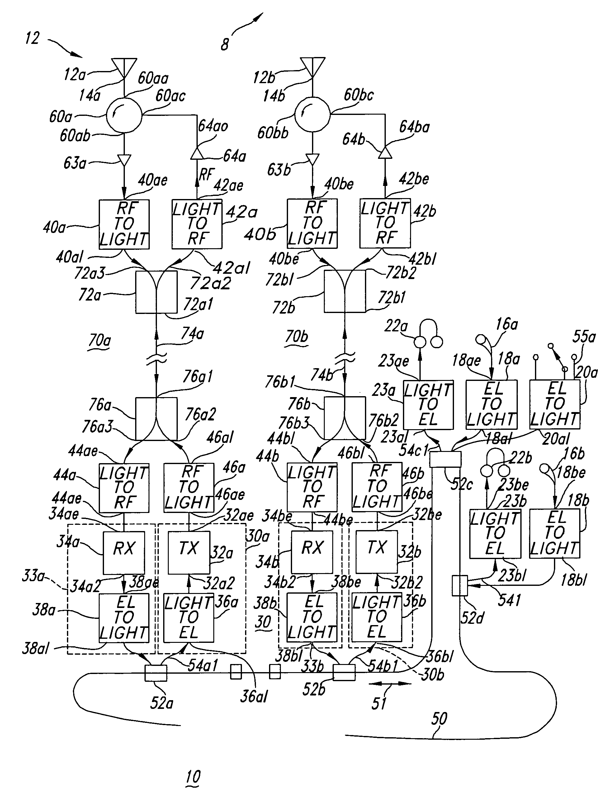
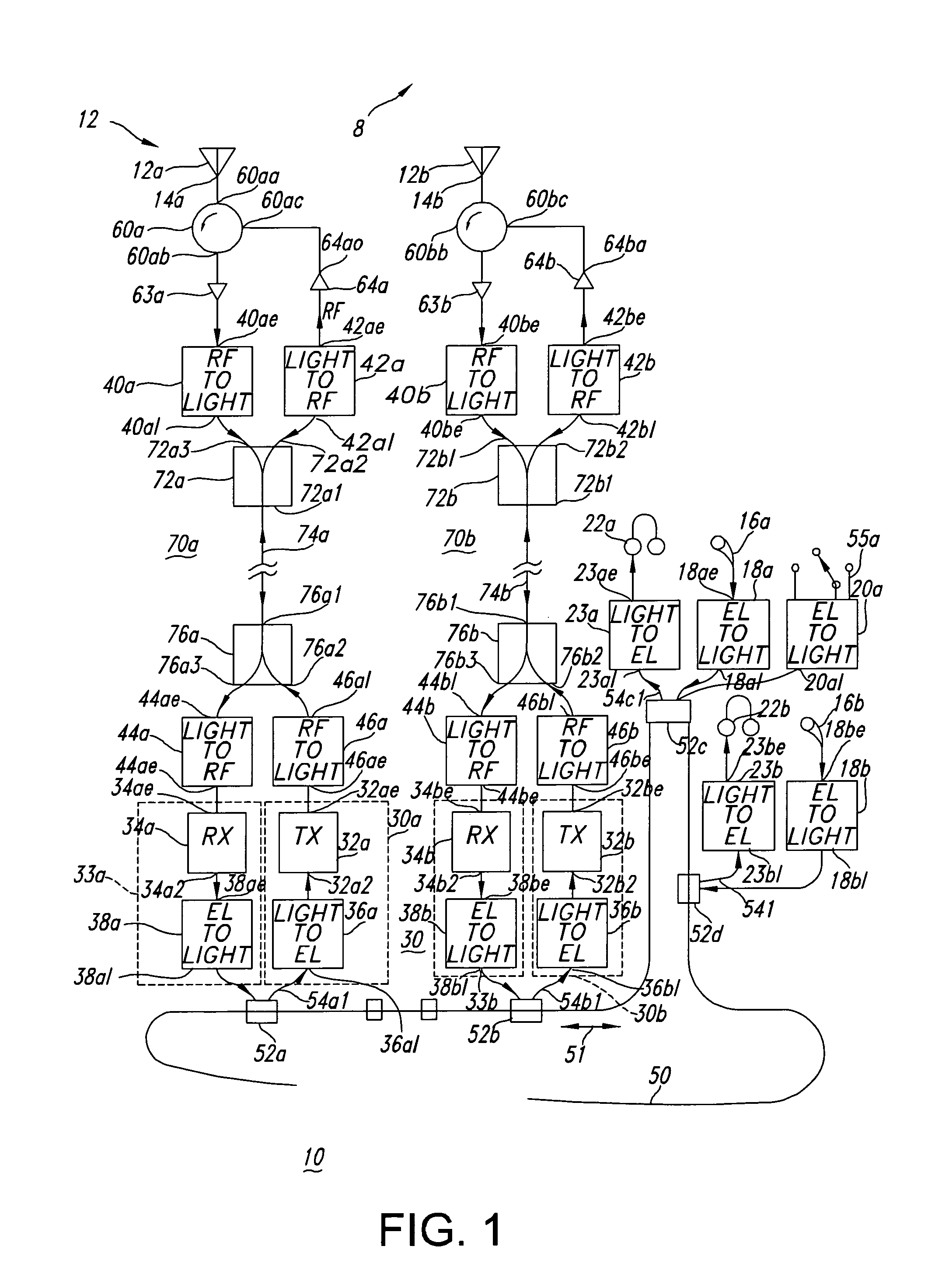
[0014]In FIG. 1, a communication system 10 includes a set 12 of antennas 12a, 12b, . . . , each of which includes a “feed” port 14a, 14b . . . . Those skilled in the art know that antennas are transducers, which transduce signals between unguided electromagnetic form in free space, indicated by the arrow 8, and guided electrical waves at the ports 14a, 14b. . . . Those skilled in the art also know that antennas are reciprocal devices, which have the same characteristics, such as beam width, pattern shape, and gain, in both transmitting and receiving modes of operation. The “feed” terminology for the port of an antenna is from an earlier time, when the reciprocity of transmission and reception were not as well known, but such language is now standard. The feed port is the port to which signals are applied for transmission, and from which received signals are taken.

[0015]In FIG. 1, the feed port 14a of antenna 12a is connected to an antenna port 60aa of a circulator 60a. Received elec...


PUM


Abstract

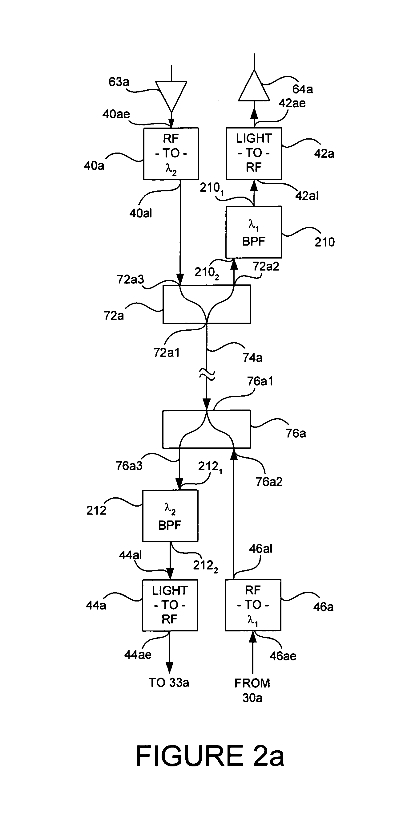
A communication system includes an optical “LAN” (50) interconnecting a plurality of information sources (16a) and sinks (22a) with a light-to-electrical converter (36a) associated with an electrical RF transmitters (32a) and an RF-to-light converter (38a) to a receiver (34a). The transmitter is coupled by way of electrical-to-light converter (46a), and the receiver is coupled by way of light-to-electrical converter (44a), and by way of a directional coupler (76a), to an end of an optical bus (74a), so that light signals representing signals to be transmitted flow in one direction, and light signals representing received signals flow in the other direction through the bus. A directional coupler (72a) at the other end of the optical bus routes the transmit light signals to a light-to-RF converter (47a) which feeds a sink or antenna (12a), and received signals from a source or antenna are routed by way of an RF-to-light converter (40a) and the directional coupler (72a) onto the optical bus (74a).

Description

FIELD OF THE INVENTION[0001]This invention relates to communication systems generally, and more particularly to communication systems using light signals to control electrical transmission and reception.BACKGROUND OF THE INVENTION[0002]It has long been recognized that aircraft and other vehicles operate most efficiently when their weight is minimized. A major contributor to the weight of modern vehicles is the load of communication equipment, including antennas, transmitters, receivers, controllers, input devices such as microphones and cameras, output devices such as monitors and headphones, and transmission lines interconnecting the various elements of the communications system.[0003]In order to reduce weight associated with the communication systems of vehicles, it is common to use full duplex operation of signal paths, so that the transmitted and received signals travel, in opposite directions, over the same transmission lines, thereby saving a substantial portion of the weight ...

Claims


Application Information

Patent Timeline
Patent Type & Authority Patents(United States)
IPC IPC(8): H04J14/02H04B10/10H04B10/24H04B10/12
CPCH04B10/25755H04J14/0298
Inventor TIEMANN, JEROME JOHNSONFREY, RICHARD LOUISBARQUIST, JR., WILLIAM SVENLOTSHAW, WILLIAM TAYLORFELDMAN, SANDRA FREEDMANSODERBERG, JOHN JESSEWHITTAKER, GEORGE ALLAN
Owner LOCKHEED MARTIN CORP
Learn More