
Clock generation system

a clock generation and clock technology, applied in the direction of pulse generators, pulse generators, electric pulse generator circuits, etc., can solve the problems of deterioration of s/n ratio, increase of clock generation system cost, etc., and achieve the effect of reducing the number of oscillations

Inactive Publication Date: 2006-08-01
ROHM CO LTD
View PDF9 Cites 6 Cited by
  • Summary
  • Abstract
  • Description
  • Claims
  • Application Information

AI Technical Summary

Benefits of technology

The invention is a clock generation system that generates multiple reference frequency clocks for MPEG format video systems. The system includes multiple PLL circuits and frequency division factors to generate the three reference clocks. The system has a reduced number of oscillation modules and sufficient signal-to-noise ratios. The system also includes a frequency division factor control circuit to switch between different frequency division factors based on a control signal. The system provides a more efficient and effective solution for generating reference clocks for MPEG format video systems.

Problems solved by technology

In this approach, however, one oscillation module must be provided for each reference frequency, which results in an increase of cost of the clock generation system.
It should be noted, however, that since the PLL circuit is in operation on the noise floor of an IC (integrated circuit) on which the PLL circuit is formed, the S / N ratio of the PLL circuit is limited by the S / N ratio of the noise floor.
Therefore, deterioration in S / N ratio is a problem that must be solved.

Method used


Image

  • Clock generation system
  • Clock generation system
  • Clock generation system

Examples


first embodiment

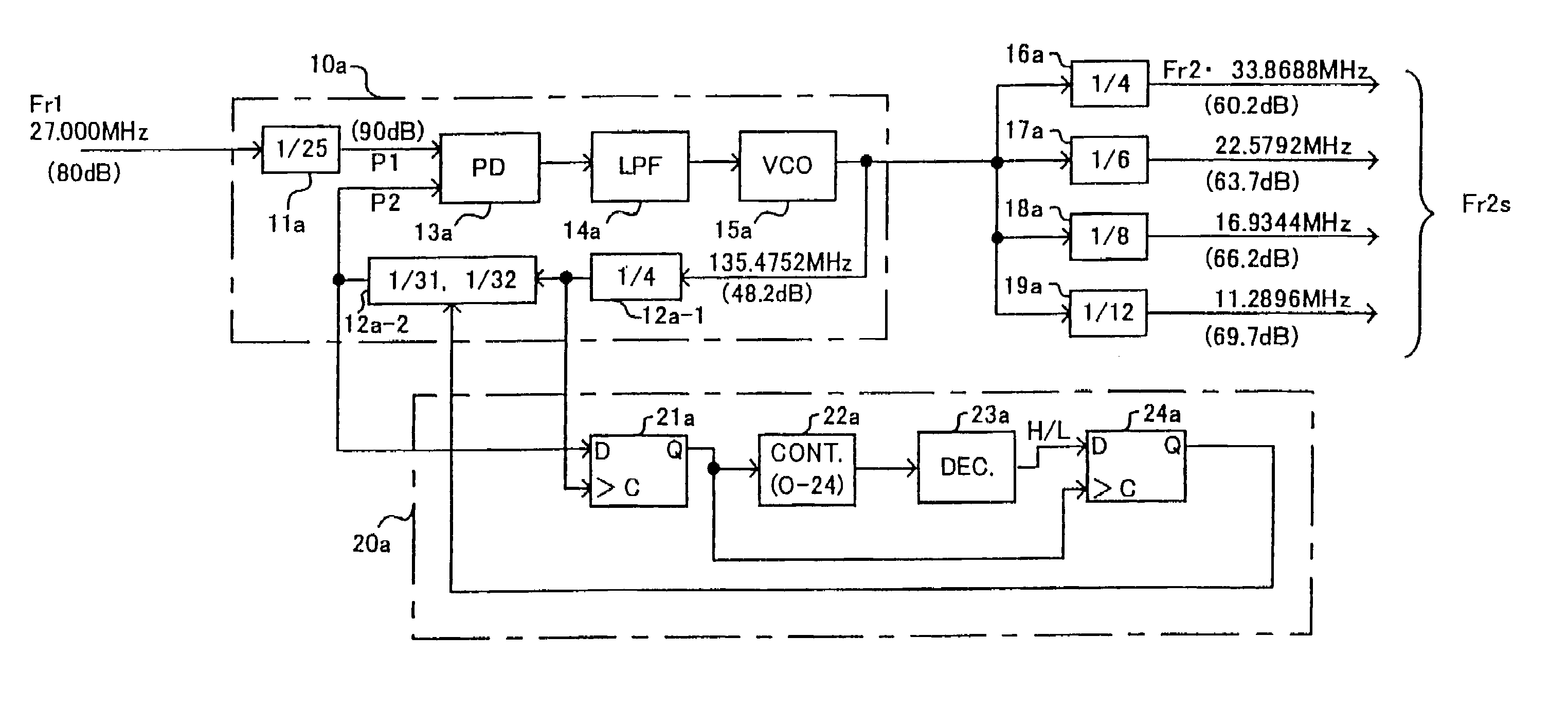
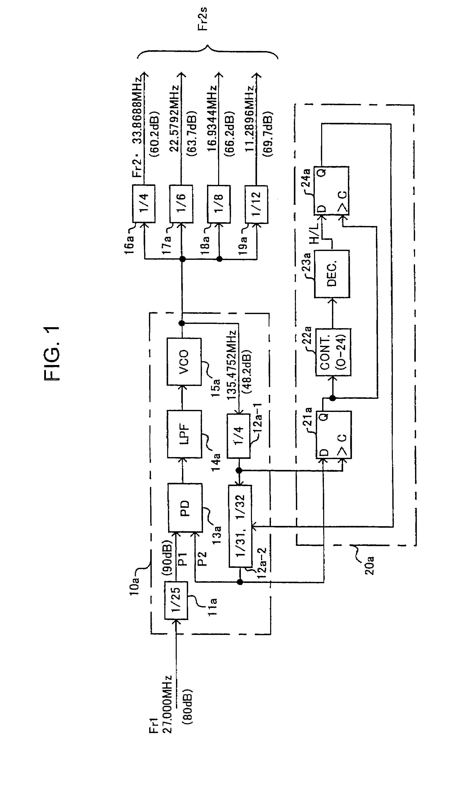
[0059]Referring to FIG. 1, there is shown a clock generation system utilizing PLL circuits in accordance with the invention. The clock generation system of FIG. 1 is designed to generate a second 33.8688 MHz series of reference frequency clocks for audio use (particularly for CDs) upon receipt of a first 27 MHz reference frequency clock for video use as a reference clock.

[0060]The S / N ratio of a PLL circuit improves in accord with frequency division factor and falls in accord with multiplication factor of the PLL circuit. It is limited by the S / N ratio of the noise floor. The frequency division ratio necessary to obtain the 33.8688 MHz second reference frequency clock from the first 27 MHz reference frequency clock using the PLL circuit is 3136 / 625, as discussed previously in connection with FIG. 5. Since there is no common divisor for 3136 and 625, the S / N ratio of the oscillation frequency signal has been low.

[0061]In the present invention, one of the frequency division factors of...

third embodiment

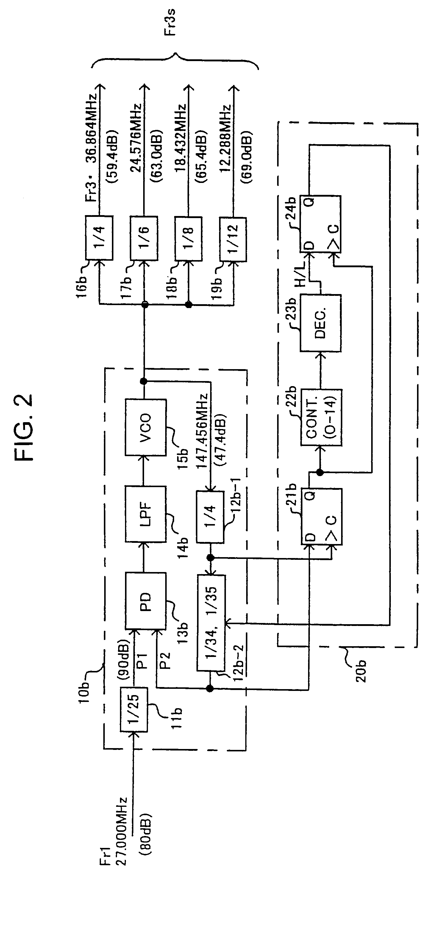
[0099]Referring to FIG. 3, there is shown a clock generation system utilizing PLL circuits in accordance with the invention. The clock generation system shown in FIG. 3 receives as a reference clock the 27 MHz first reference frequency clock Fr1, and generates the 27 MHz first reference frequency clock series Fr1s for video use, a 33.8688 MHz second reference frequency clock series Fr2s for audio use (particularly for CDs), and a 36.864 MHz third reference frequency clock series Fr3s for audio use (particularly for DVDs).

[0100]As shown in FIG. 3, the section of the third embodiment for generating the 33.8688 MHz clock series Fr2s is the same as that of the first embodiment shown in FIG. 1, and the section of the third embodiment for generating the 36.864 MHz clock series Fr3s is the same as that of the second embodiment shown in FIG. 2. The third embodiment is further provided with an additional section for generating, from the first reference clock Fr1 inputted as a reference frequ...


PUM

PropertyMeasurementUnit
frequenciesaaaaaaaaaa

Abstract

A frequency-divided reference frequency clock is provided as a reference input to a phase comparator. An oscillation frequency signal of a controllable oscillator, having a frequency associated with another reference frequency clock, is frequency divided by a frequency division factor switching type comparison-input frequency division circuit. The resultant frequency-divided clock is provided as a comparison input to the phase comparator. The frequency division factor of the comparison-input frequency division circuit is switched from one to another based on a frequency division factor control signal to generate an oscillation frequency signal having a predetermined frequency ratio relative to another reference frequency clock. Thus, three reference frequency clocks of 27 MHz, 33.8688 MHz, and 36.864 MHz in accord with the MPEG format are obtained with a sufficient S / N ratio.

Description

FIELD OF THE INVENTION[0001]This invention relates to a clock generation system for generating a first through third reference frequency clocks having predetermined frequency ratios relative to a given frequency clock. More particularly, the invention relates to a clock generation system for generating a multiplicity of reference frequency clocks necessary for DVD (Digital Versatile Disc) systems or DVC (Digital Video Cassette recorder) systems.BACKGROUND OF THE INVENTION[0002]As is well known, existing DVD systems such as a DVD player, DVD-R and DVD-RW drives, and MPEG (Moving Picture Experts Group) format systems require multiple reference frequency clocks. These reference frequency clocks include at least a first series of reference frequency clocks for video use based on a 27 MHz clock (the series referred to as 27 MHz first clock series), a second series of reference frequency clocks for audio use based on a 33.8688 MHz clock (particularly for CDs, having frequencies that are i...

Claims


Application Information

Patent Timeline
Patent Type & Authority Patents(United States)
IPC IPC(8): H03B19/12H03K21/00H03K23/00H03K3/03H03L7/00G11B20/14H03L7/07H03L7/099H03L7/183H03L7/197H03L7/23
CPCH03L7/23H03L7/1974H03L7/07H03L7/099
Inventor FUJIWARA, MASAYU
Owner ROHM CO LTD
Learn More