
Low noise amplifier and related method

a low noise amplifier and amplifier technology, applied in the direction of low noise amplifier, amplifier combination, gain control, etc., can solve the problems of not being able to successfully suppress the undesired noise, not being able to generate a frequency response with such a great bandwidth, and not being able to achieve the effect of low noise, low noise amplifier and low nois

Active Publication Date: 2006-08-01
REALTEK SEMICON CORP
View PDF8 Cites 28 Cited by
  • Summary
  • Abstract
  • Description
  • Claims
  • Application Information

AI Technical Summary

Benefits of technology

The invention provides a low noise amplifier with a switched bandwidth instead of a fixed bandwidth to solve the problem of high noise levels. The amplifier includes a switched loading circuit with multiple loading units that determine the center frequency of the amplifier. A converter converts the input signal into a loading current, which is then passed through the enabled loading unit to generate the output signal. The invention allows for efficient filtering of the input signal and reduces noise levels.

Problems solved by technology

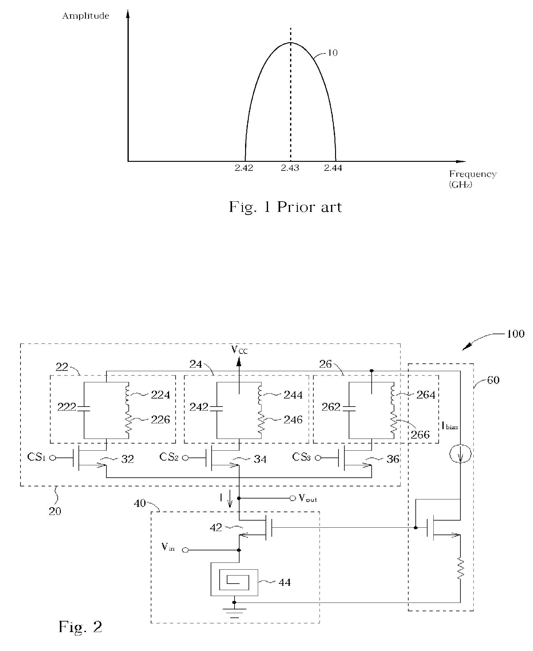
However, this kind of LNA is not applicable in a wideband communication system especially when the wideband communication system uses a high-frequency carrier to transfer data.
Therefore, the combination of the inductor and the capacitor according to the prior art narrow-band LNA is unable to generate a frequency response with such a great bandwidth.
However, if a prior art wide-band LNA is adopted, much of the undesired noise could not be successfully suppressed through a single filtering bandwidth, and is injected into the ultra-wideband communication system, which degrades the signal quality.

Method used


Image

  • Low noise amplifier and related method
  • Low noise amplifier and related method
  • Low noise amplifier and related method

Examples


Embodiment Construction

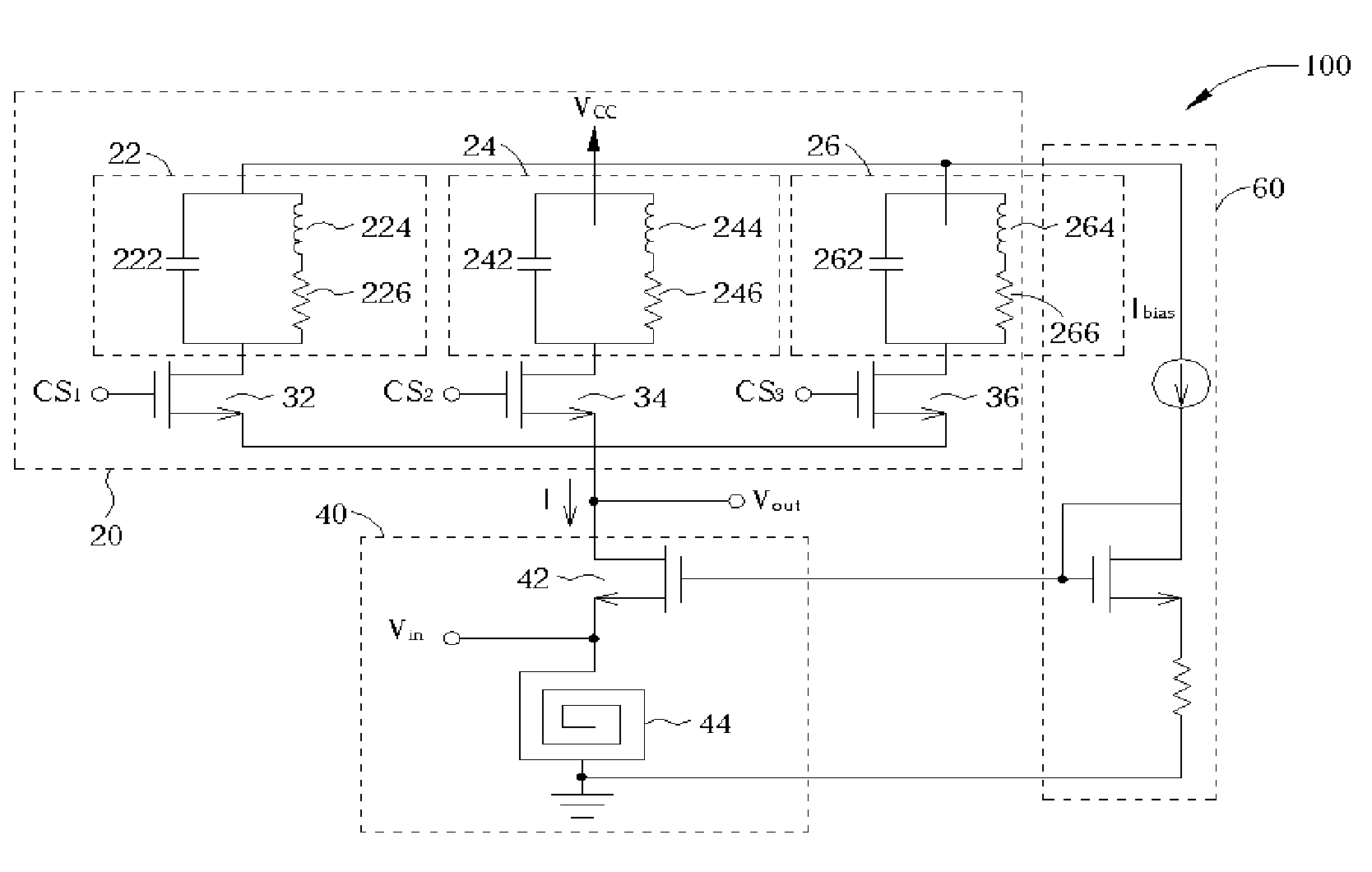
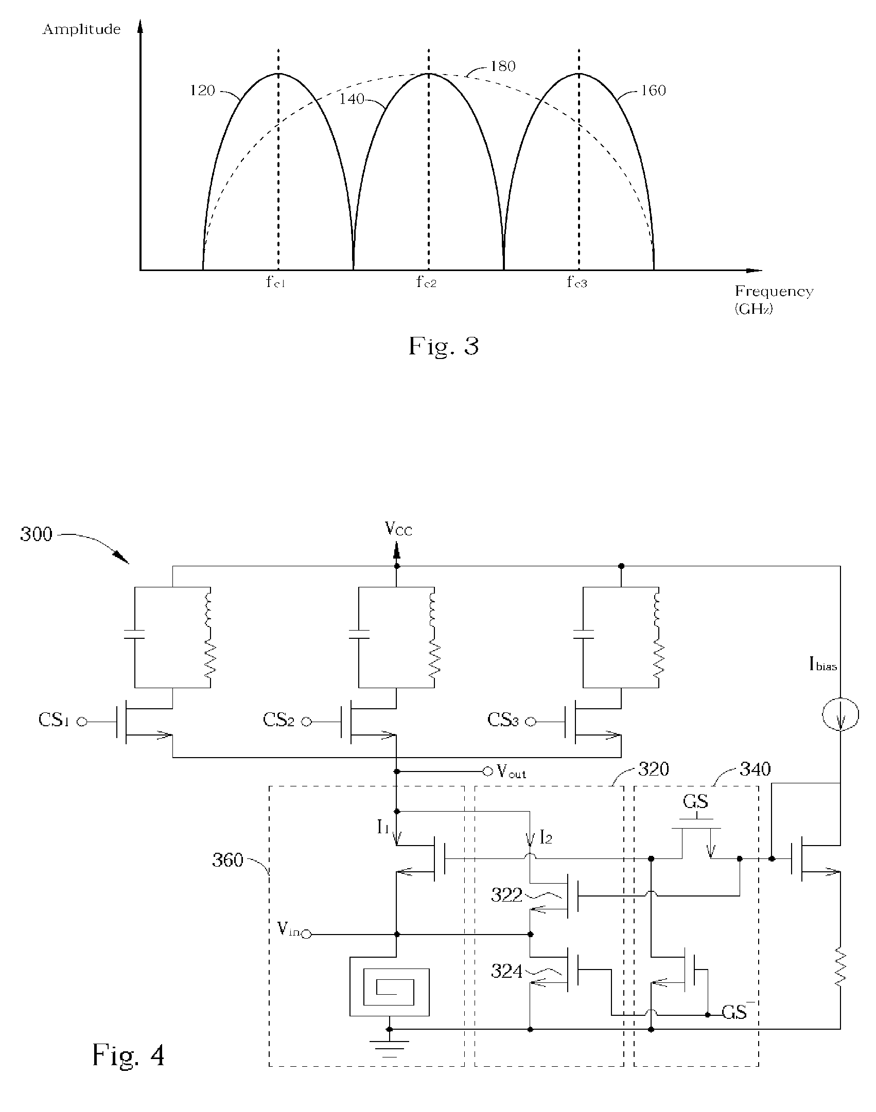
[0015]Please refer to FIG. 2, which is schematic diagram of a low noise amplifier (LNA) 100 according to an embodiment of the present invention. In this embodiment, the LNA 100 is applied to a wideband communication system (e.g. an ultra-wideband communication system). The LNA 100 includes a switched loading circuit 20, a voltage to current transformer 40, and a bias circuit 60. The switched loading circuit 20 is used to provide a switched loading in order to tune a desired center frequency and a desired bandwidth. As shown in FIG. 2, the switched loading circuit 20, in this embodiment, contains three loading units 22, 24, 26, and three switches 32, 34, 36. NMOS transistors implement all of the switches 32, 34, 36, respectively. However, it is well-known that an NMOS transistor or a PMOS transistor can be adopted to function as a transistor switch. The implementation of the switches 32, 34, 36 shown in FIG. 2 is only meant to serve as an example and is not meant to be taken as a lim...


PUM


Abstract

A low noise amplifier (LNA) for filtering an input signal to generate an output signal. The low noise amplifier includes a switched loading circuit having a plurality of loading units, each of the loading units determining a corresponding center frequency of the low noise amplifier. The switched loading circuit selectively enables a loading unit having the desired corresponding center frequency. At least one converters coupled to the switched loading circuit converts a voltage of the input signal into a loading current and passes the loading current through the enabled loading unit to generate the output signal.

Description

BACKGROUND OF INVENTION[0001]1. Field of the Invention[0002]The present invention relates to a low noise amplifier, and more particularly to a low noise amplifier and related method in a wideband communication system.[0003]2. Description of the Prior Art[0004]A low noise amplifier (LNA) is a common device used to filter out the noise of input signals received at the front ends of communication systems. Generally speaking, the LNA is capable of decreasing most of the incoming noise and amplifying a desired signal within a certain frequency range to increase the signal to noise ratio (SNR) of the communication system and improve the quality of received signal as well. Because the desired signal is transmitted via a carrier, the frequency range of the desired signal is supposed to be near the carrier frequency. Therefore, the LNA is designed to magnify an input signal with a frequency close to the carrier frequency and attenuate an input signal with a frequency far away from the carrie...

Claims


Application Information

Patent Timeline
Patent Type & Authority Patents(United States)
IPC IPC(8): H03F3/04
CPCH03F3/189H03F2200/372H03F2200/294
Inventor RAZAVI, BEHZADKANG, HAN-CHANG
Owner REALTEK SEMICON CORP
Learn More