
Method for producing a toothbrush

a toothbrush and production method technology, applied in the field of toothbrush production, can solve the problems of large increase in injection time and cooling time, tendency to cavitation of handle parts with relatively large cross sections, and prolongation of injection molding process, so as to facilitate the formation of handles with distinct different portions. , the effect of large cross section

Inactive Publication Date: 2006-08-01
TRISA HLDG AG
View PDF19 Cites 58 Cited by
  • Summary
  • Abstract
  • Description
  • Claims
  • Application Information

AI Technical Summary

Benefits of technology

The present invention proposes a method for making toothbrushes with solid handles of large cross section. This method guarantees short injection intervals and allows for the simultaneous molding of multiple handles using a plural cavity die set. The use of plastic supply injectors may also be employed. The technical effect of this invention is to improve the production efficiency and quality of toothbrushes with solid handles.

Problems solved by technology

However, this kind of handle design entails a number of disadvantages from the point of view of production technology.
Not only is more material used as a result of the greater volume of the handle; the injection time and cooling time are also hugely increased by the greater mass, and the injection-molding process is thus prolonged (longer molding time).
In addition, such handle parts with a relatively large cross section have a tendency to cavitation (i.e. formation of air bubbles) which are visible in handles made of a transparent material and detract from the esthetic effect of the toothbrush.

Method used


Image

  • Method for producing a toothbrush
  • Method for producing a toothbrush
  • Method for producing a toothbrush

Examples


Embodiment Construction

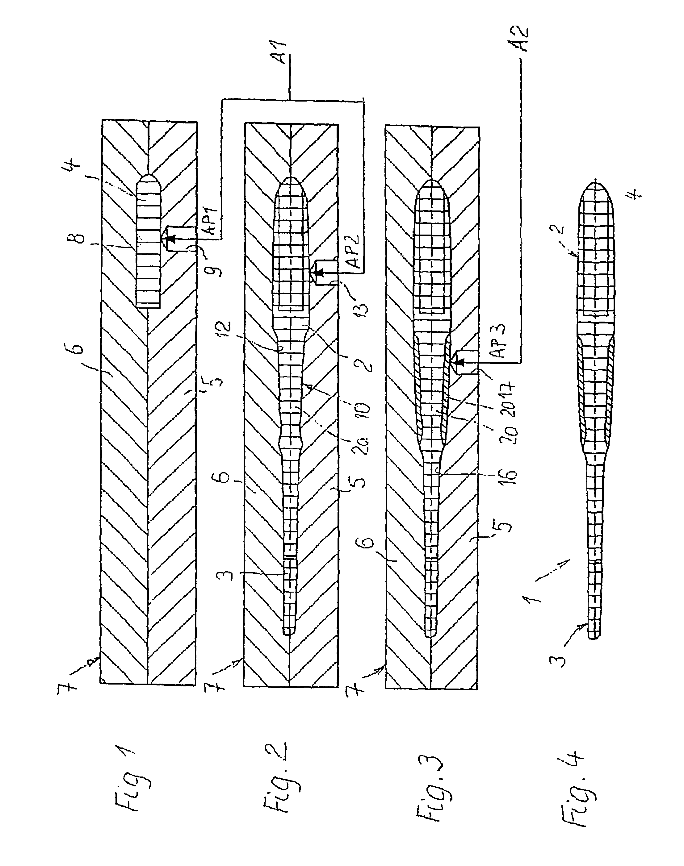
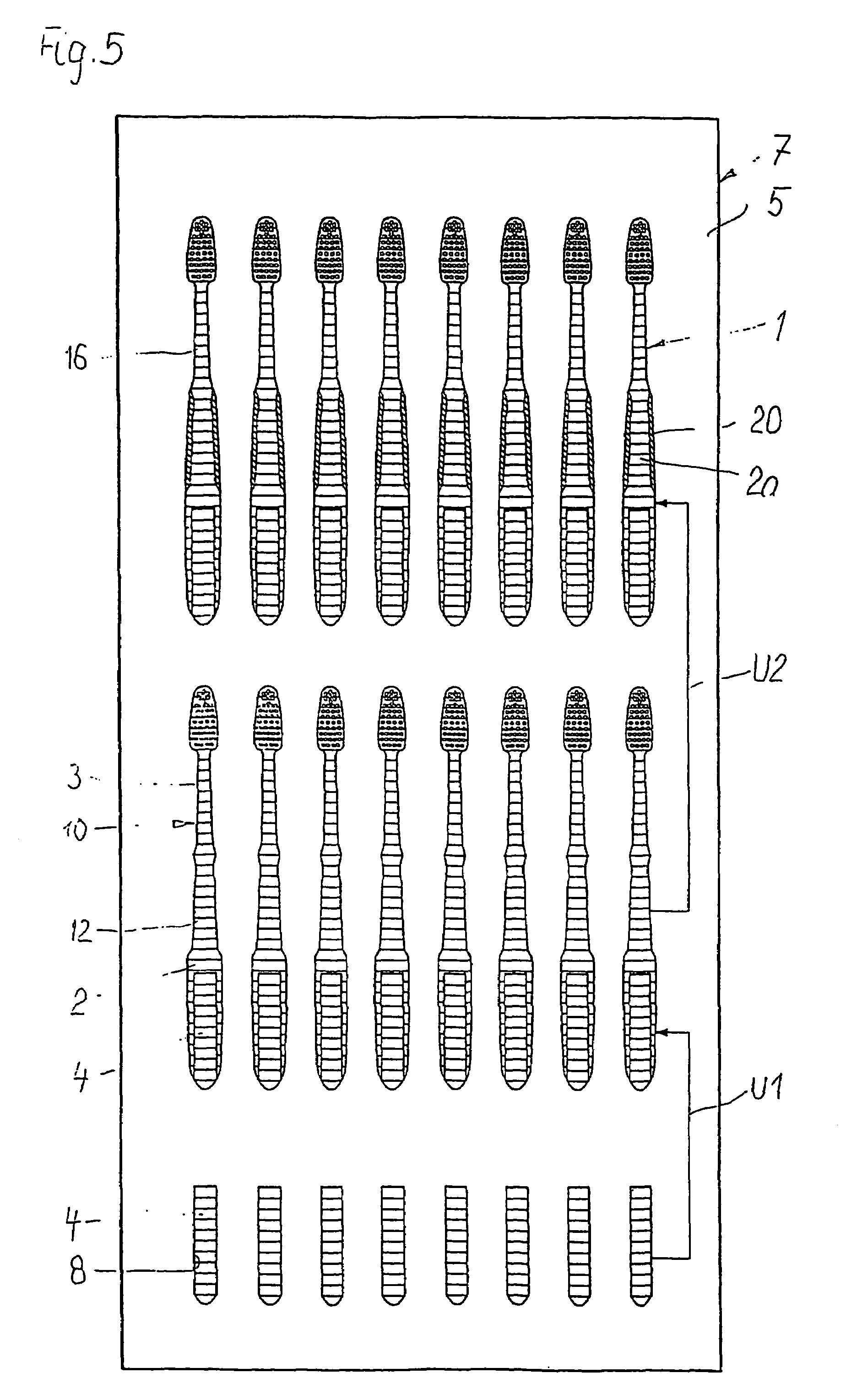
[0019]To produce a toothbrush 1 which is shown in FIG. 4 and whose handle 2 has a larger cross section than the front head part 3 provided for securing the bristles or tufts, an inner part 4 of the handle 2 is first prepared in a first step shown in FIG. 1. For this purpose, a first portion of the first material component provided for the handle 2 (and if appropriate also for the head part 3) is injected into a first cavity a formed between two parts 5, 6 of an injection mold 7. The first injection point for the first material component delivered from a first unit A1 is indicated by AP1 in FIG. 1, while the injection channel or injection nozzle provided for this is indicated by 9.

[0020]As can be seen from FIG. 5, the injection mold 7 is provided for the production of a plurality of toothbrushes 1, if appropriate eight tooth brushes 1. After partial cooling and hardening (as soon as sufficient inherent stability is achieved), the inner parts 4 injected in the first step according to ...


PUM

PropertyMeasurementUnit
areaaaaaaaaaaa
elastically resilientaaaaaaaaaa
sizeaaaaaaaaaa

Abstract

A method for efficiently producing injection molded toothbrush handles wherein two or more adjacent cavities in a mold are respectively configured to mold a first portion of a handle and a second portion of a handle, wherein upon injection molding of the first portion in a first cavity, the second portion is simultaneously injected into a second cavity into which a previously molded fist portion has been placed after its removal from the first cavity, thereby to immediately contact the previous first portion with the newly injected second portion. A third portion may also be injected into a third cavity into contact with a previously injection molded contacting first and second toothbrush handle portion. In this manner, seriatim transfer of the said portions between cavities enhances product output. The handle may include transparent or translucent portions.

Description

CROSS-REFERENCE TO RELATED APPLICATIONS[0001]The subject application is based upon International Application PCT / CH01 / 00720 filed Dec. 17, 2001, now WO 02 / 052982 dated Jul. 11, 2002.BACKGROUND OF THE INVENTION[0002]WO-A-94 / 05183 discloses a method for producing a toothbrush consisting of two different material components, in which method, in a first step, the main body of the toothbrush is injected from a first material component, for which purpose a first cavity is provided. Thereafter, in a second cavity, a further material component, for example an elastic and / or nonslip material, is injected onto various parts of the main body. The main body has a relatively narrow cross section both in its area supporting the bristles and also in its handle area.[0003]In order to improve the grip of toothbrushes and to permit comfortable handling, it is advantageous to make the toothbrush relatively solid in its handle area, i.e. to give the handle a relatively large cross section. However, thi...

Claims


Application Information

Patent Timeline
Patent Type & Authority Patents(United States)
IPC IPC(8): B29C45/02B29C45/14B29C45/16A46B5/02A46D3/00
CPCA46B5/02A46D3/005B29C45/16A46B2200/1066B29L2031/425B29C45/1615B29C45/1676B29C2045/1682
Inventor STRAHLER, RETO
Owner TRISA HLDG AG
Learn More