Casing member and method for manufacturing the same

a technology of casing assembly and main body, which is applied in the manufacture of contact member cases/bases, electrical devices, combination devices, etc., can solve the problems of deterioration in performance, high pressure in the casing, and partially broken sealing parts of the casing, so as to reduce the tightening for

Inactive Publication Date: 2006-08-01
TOKAI KOGYO CO LTD
View PDF33 Cites 15 Cited by
  • Summary
  • Abstract
  • Description
  • Claims
  • Application Information

AI Technical Summary

Benefits of technology

[0009]According to the first aspect of the invention, with respect to the inside and the outside of the casing, the first vent hole provided in the casing member main body of the casing member and the second vent hole of the cover member are connected to each other through the permeable sheet covering the whole of the first vent hole, and ventilation of the air and moisture in the air is possible between the inside and the outside of the casing. However, infiltration of a water droplet, an oil droplet, etc. from the outside of the casing to the inside is prevented. Since the second vent hole provided in the cover member is very small as compared with the first vent hole of the casing member main body, even in the case where an object strikes on the casing, it directly strikes on the cover member and hardly strikes on the inside permeable sheet. That is, since the permeable sheet is protected by the cover member disposed at its outside, the damage, such as rupture or peeling, of the permeable sheet can be prevented.
[0031]According to the twelfth aspect of the invention, in addition to the effect of any one of the seventh to eleventh aspects of the invention, not only setting of the cover member becomes easy, but the cover member does not move toward a side by resin pressure at the time of injection molding. Therefore, as compared with the case where the positioning fitting part is not provided, the tightening force of the mold can be made small. In the case where the positioning fitting part is not provided, since the movement of the cover member toward the side is restrained by the tightening force, a large tightening force becomes inevitably necessary, and there is a fear that the cover member or the permeable sheet is damaged by this. However, this fear can be eliminated by providing the positioning fitting part to lessen the tightening force.

Problems solved by technology

As a result, the pressure in the casing becomes high, and there is a case where a sealed portion of the casing is partially broken.
Further, because of the temperature rise due to the heat generation, there is a danger that an erroneous operation will occur in the equipment such as the inner computer, or a deterioration in performance will be caused.
When a force exceeding a limit is applied as a result of the contact, this permeable sheet is damaged.
For example, there is a danger that a pointed end of a screw driver will tear the permeable sheet carelessly to make a hole.
Since there is a fear that the permeable sheet will be damaged during this bonding operation, excessive attentiveness is required for the bonding operation of the permeable sheet.
(3) Since a bonding force is apt to vary by a variation in the amount of adhesive used, or the press force of the permeable sheet, a uniform and stable bonding state is hard to obtain over the whole bonded portion.

Method used


Image

  • Casing member and method for manufacturing the same
  • Casing member and method for manufacturing the same
  • Casing member and method for manufacturing the same

Examples


first embodiment

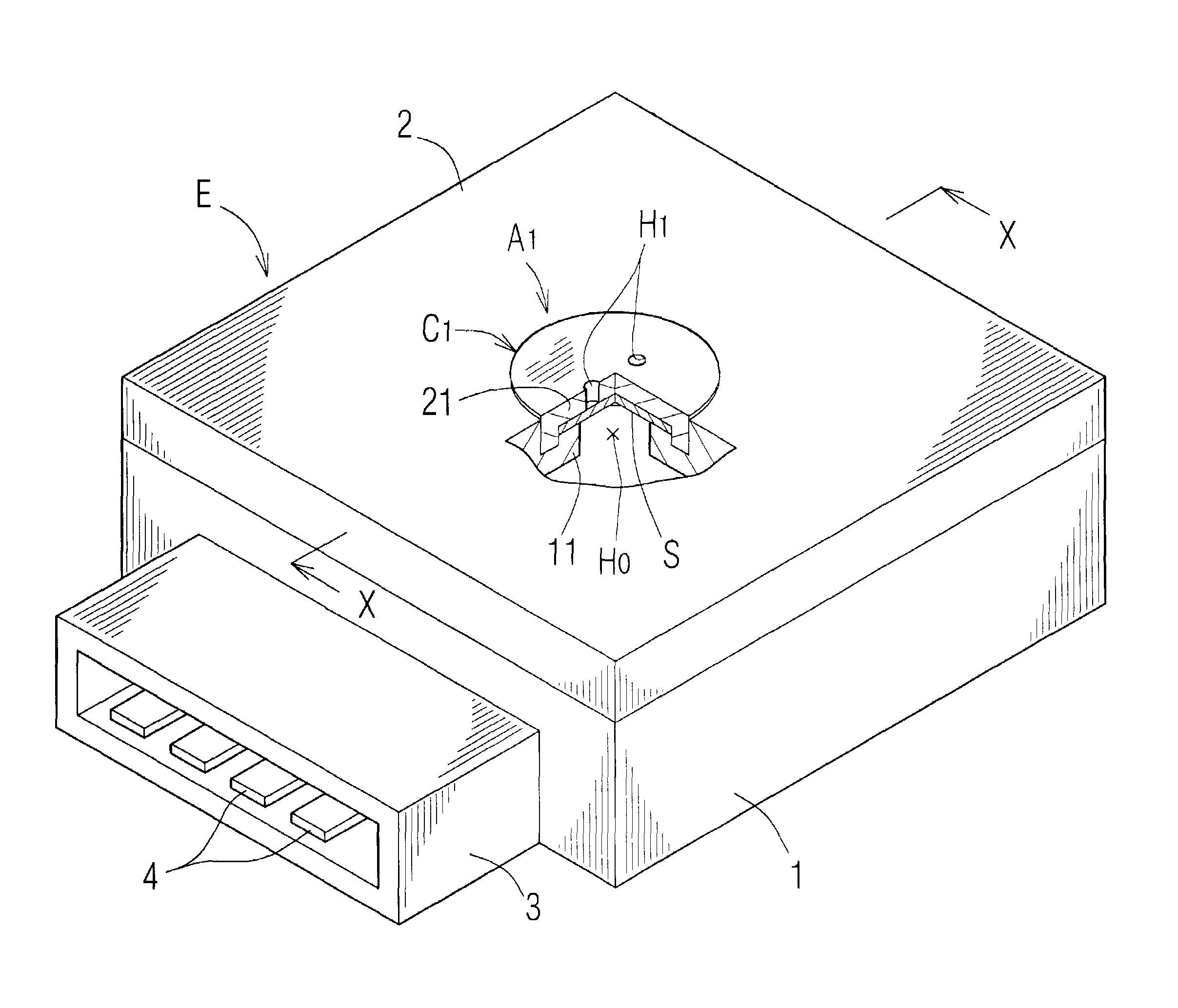
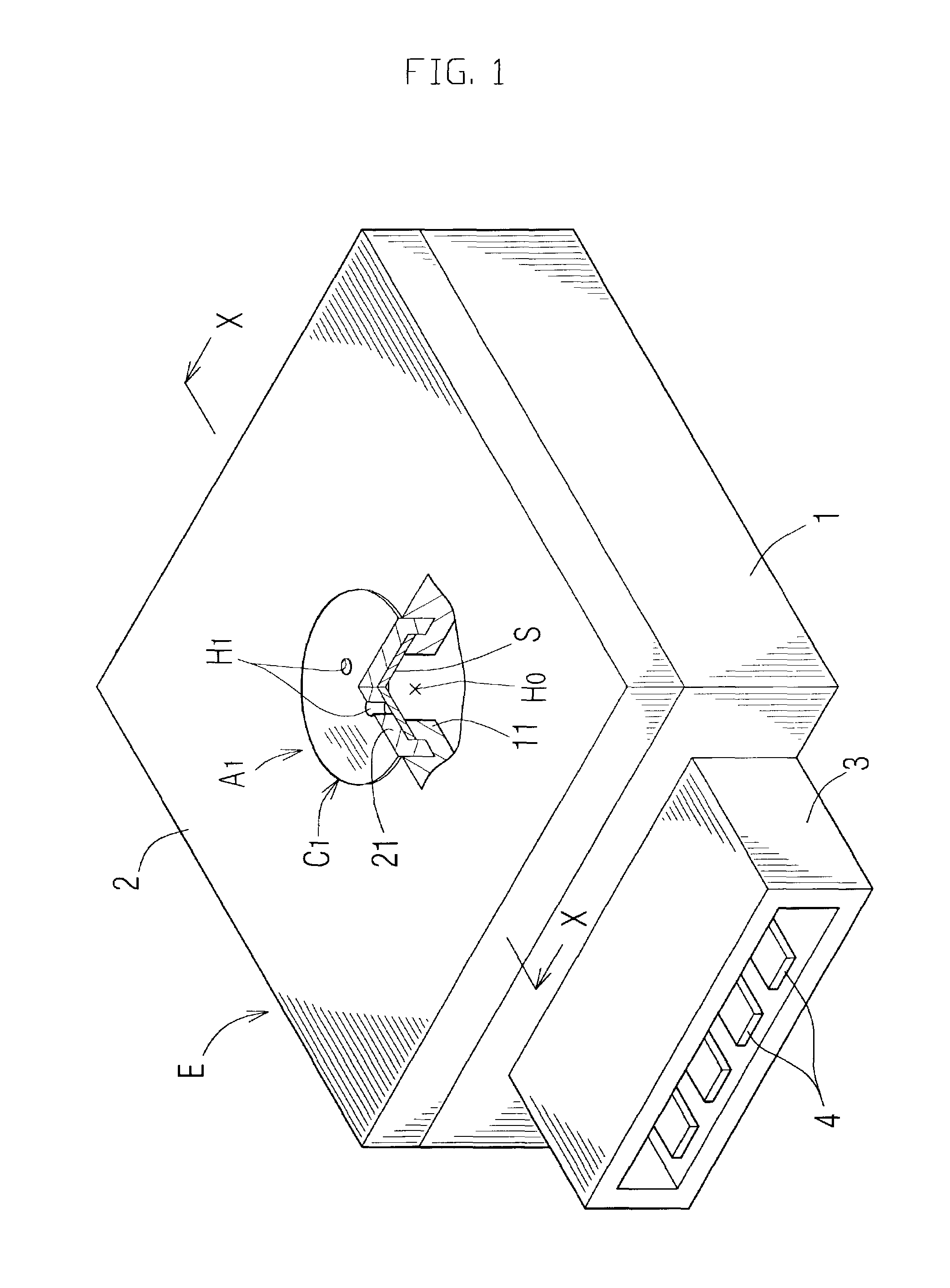
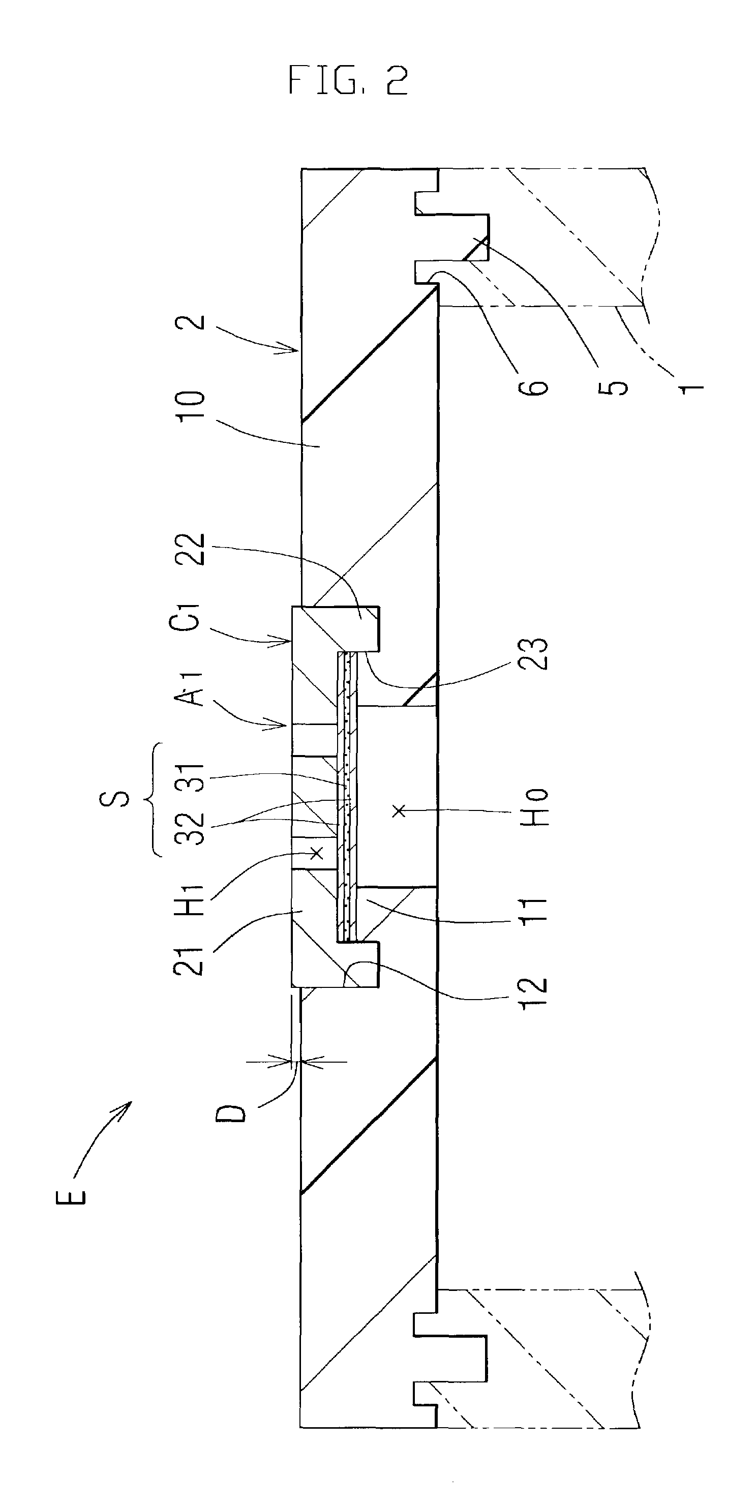
[0052]Hereinafter, the present invention will be described in more detail by explaining plural embodiments. FIG. 1 is a perspective view of a connector casing E as a casing assembly using a resin casing component member of the invention, and FIG. 2 is a sectional view taken along line X—X of FIG. 1 and shows a section of a cover 2 as one of component members. With respect to the illustration of a permeable sheet in FIG. 2 or the like, since the illustration is impossible to provide in original size expression, its thickness is considerably enlarged and is illustrated. Moreover, in the case where a permeable sheet appears in both a perspective view of a resin casing and its sectional view, the size of the permeable sheet with respect to the resin casing is neglected and is illustrated.

[0053]This connector casing E comprises a casing main body 1 which is one of the component members of the casing assembly and is injection molded out of synthetic resin. The substantially plate-shaped c...

second embodiment

[0093]Subsequently, other embodiments of the invention will be described. In respective portions of the other embodiments described below, the same portions as the already described portions are denoted by the same symbols, and the explanation and illustration are made. In a cover 2 of a second embodiment shown in FIG. 8 to FIG. 11, a cover insert member C2 of a permeable member A2 is different from that in the already described embodiment. As a result, a structure of integration of the permeable member A2 and a cover main body 10 is different. This cover member C2 has such a structure that an annular anchor part 24 is provided protrusively outside in a radius direction and integrally to have a step toward the inside at the outer peripheral side of the annular protrusion 22 of the foregoing cover insert member C1 [see FIG. 9]. Then, this cover insert member C2 has a merit that at the time of injection molding of the cover 2, it is embedded in the cover main body 10 and an undercut p...

fourth embodiment

[0098]the invention will be described below. As shown in FIG. 14 and FIG. 15, this cover insert member C4 has the same structure as the above cover insert member C2, except for portions of small vent holes H4, and has such a structure in that the small vent holes H4 are formed at four equally spaced places on the same circumference in the main body part 21. A clearance hole part H10 of a circular shallow groove shape communicating with all of the four small vent holes H4 is formed at the back side of the main body part 21. The clearance hole part H10 is a circular recess part provided at the bottom of the receiving recess part 23 of the cover insert member C4 to be slightly recessed to the front side, and is provided so that when the cover insert member C4 is integrated with the cover main body 10, it faces the large vent hole H0 through the permeable sheet S.

[0099]Accordingly, the area of the small vent holes H4 formed in the cover member C4 at the side of the permeable sheet S bec...


PUM

PropertyMeasurementUnit
thicknessaaaaaaaaaa
sizeaaaaaaaaaa
sizeaaaaaaaaaa

Abstract

A connector casing E required to have a sealing property includes a cover 2. The cover 2 has a cover main body 10 provided with a large vent hole H0 passing through the connector casing E in an inward and outward direction and having a predetermined inner diameter size. A permeable sheet S, which permits permeation of a gas and prevents permeation of a liquid and a solid, is integrally joined to an outside peripheral part of the large vent hole H0 so as to cover the large vent hole H0 from its outside. A cover insert member C is disposed outside the permeable sheet S to cover the permeable sheet from the outside, and a ring-shaped protrusion 22 is hermetically joined to the casing main body 10. The cover insert member C1 is provided with a small vent hole H1 which has an inner diameter smaller than the large vent hole H0 and communicates with the large vent hole H0 through the permeable sheet S.

Description

FIELD OF THE INVENTION[0001]The present invention relates to a casing main body and a cover as component members of a casing assembly, and particularly to a casing component member in which the outside of a large vent hole provided in at least a part of the member is covered with a permeable member, and a method of manufacturing the same.BACKGROUND ART[0002]As an example of a casing assembly required to have the foregoing performance, as shown in FIG. 20, a connector casing E′ for housing a microcomputer for controlling a vehicle engine or the like, or various electric·electronic equipments can be cited. This connector casing E′ is fitted in an engine room or a vehicle compartment, and is used to control the operation of an engine or to control various driving devices of the vehicle. In order to maintain the control to be accurately carried out without an erroneous operation, that is, in order to always accurately and stably operate the housed microcomputer or various electric·elect...

Claims


Application Information

Patent Timeline
Patent Type & Authority Patents(United States)
IPC IPC(8): B01D19/00H05K5/02B29C45/14B29C45/26B29K105/20B29L9/00H01R13/52H01R43/18H05K5/06
CPCB29C66/71B29C66/7292B29C66/72941H05K5/068H05K5/0213B29C66/5346B29C66/5326B29C66/534B29K2027/18B29C66/8322B29C65/42B29C65/02B29C65/4825B29C65/5057B29C66/712B29C66/61B29C66/1222B29C66/1224B29C66/12445B29C66/12469B29C66/72343H05K5/0215B29K2023/06B29K2023/12B29K2059/00B29K2067/00B29K2077/00
Inventor HARA, KOUICHIFUKUNISHI, ATSUSHI
Owner TOKAI KOGYO CO LTD
Why Eureka
Try Eureka