Integrated fixed film activated sludge system using gravity assisted mixing

a technology of gravity assisted mixing and activated sludge, which is applied in biological water/sewage treatment, filtration separation, and separation processes, etc., can solve the problem of limiting the treatment capacity of existing activated sludge systems, and achieve the effect of high degree of treatment and process flexibility

Inactive Publication Date: 2006-08-01
VAN DRIE GERHARDT
View PDF28 Cites 23 Cited by
  • Summary
  • Abstract
  • Description
  • Claims
  • Application Information

AI Technical Summary

Benefits of technology

[0018]Integrated Fixed Film Activated Sludge Systems (IFAS) add the benefits of Fixed Film systems into the suspended growth Activated Sludge process. Activated Sludge has process flexibility and provides a high degree of treatment. Fixed Film processes are inherently stable and resistant to organic and hydraulic shock loadings. Placing Fixed Film media into Activated Sludge basins combines the advantages of both of these systems.

Problems solved by technology

The additional biomass provided by placing Fixed Film media directly into the suspended growth reactor does not increase clarifier solids loading (a factor that often limits the treatment capacity of existing Activated Sludge systems).

Method used


Image

  • Integrated fixed film activated sludge system using gravity assisted mixing
  • Integrated fixed film activated sludge system using gravity assisted mixing
  • Integrated fixed film activated sludge system using gravity assisted mixing

Examples


second embodiment

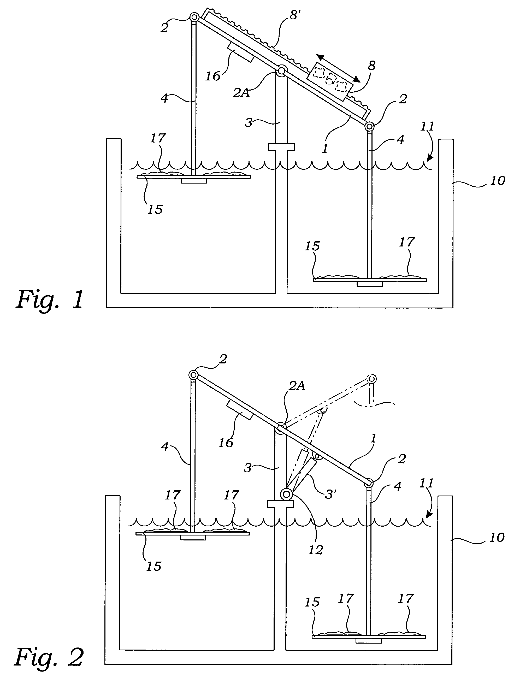
[0043]In the invention, the unbalancing means comprises at least one linear actuator 3′, such as a hydraulic or air cylinder. As shown in FIG. 2, the actuator 3′ is pivotally engaged with the beam 1 in a manner whereby linear actuation causes the beam 1 to cyclically move in the tilting motion. Clearly it would be within the skill of one knowledgeable in this art to configure electrical and air or hydraulic lines in such manner as to enable the invention to perform this simple function. FIG. 2 shows the actuator 3′ in solid line at is retracted position and also in phantom in its extended position.

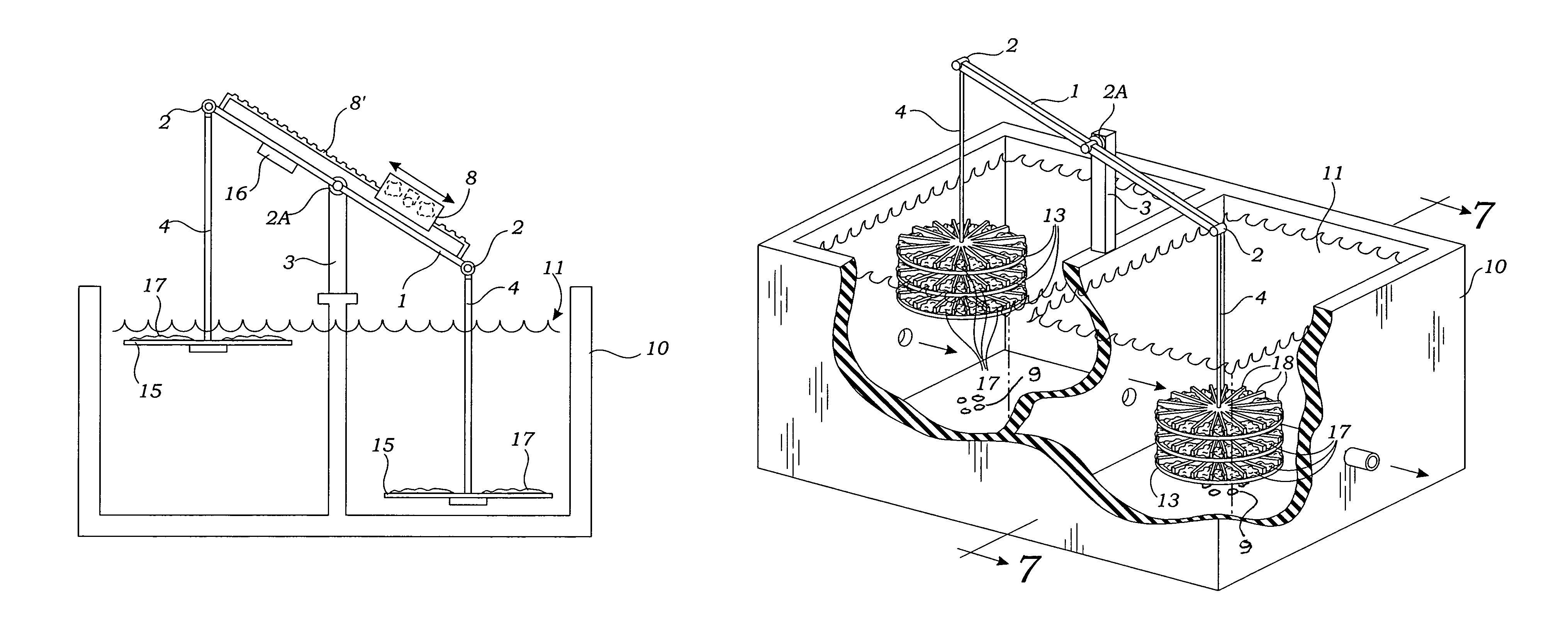
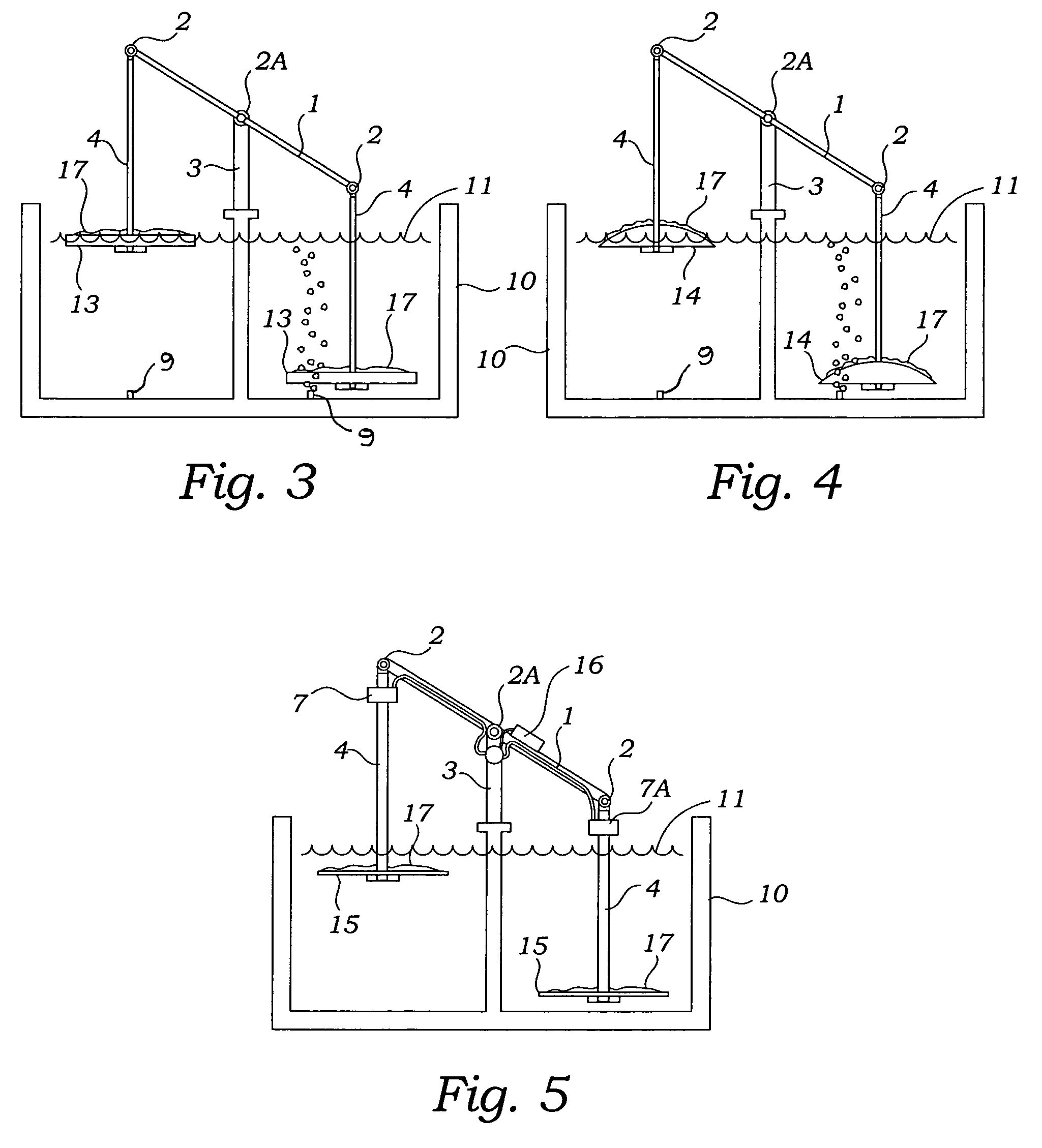
[0044]In a third embodiment of the invention, shown in FIGS. 3 and 4, one or more diffuser pipes 9 deliver gas bubbles from below under the mixing plates that require buoyancy and the delivery of bubbles is alternated from side to side typically driving the lower mixing plates upward primarily by the buoyancy of gas delivered under the plates 13, 14, or 15. In this embodiment, the plates t...

fourth embodiment

[0045]In a fourth embodiment shown in FIG. 5, the unbalancing means comprises a pair of liquid reservoirs 7 and 7A, with one of the liquid reservoirs attached near each one of the ends of the beam 1. A liquid pump 5 is engaged with the pivot support 3. The reservoirs 7, 7A and the pump 5 are in mutual communication for moving the liquid, preferably water or other relatively heavy liquid, e.g., Mercury, cyclically from one of the reservoirs to the other of the reservoirs thereby causing the tilting motion of the beam 1 by means of its unbalancing. In this embodiment, switch 16 determines the direction of pump 5, so that when one side of the beam 1 is at it apogee, the pump 5 reverses the fluid flow and starts pumping the fluid to the reservoir 7 or 7A that is at it apogee. In fact, due to hysteresis effects, the reversal of pump 5 is started prior to the reservoir that is being filled reaching its low point. In this manner momentum of the beam 1, arms 4 and the mixing blades 15 is ab...


PUM

PropertyMeasurementUnit
weightaaaaaaaaaa
electric currentaaaaaaaaaa
movementaaaaaaaaaa

Abstract

A beam is pivotally supported at a fixed pivot support, the beam movable in cyclic tilting motion such that ends of the beam move vertically in mutually opposing directions. The ends of the beam are pivotally engaged with vertical arms extending downwardly. The arms terminate with mixing plates immersed within the fluid so that the mixing plates cause fluid mixing as the tilts. A fixed film biomass is engaged with the surfaces of the plates for improved bio-processing within the tanks.

Description

RELATED APPLICATIONS[0001]This application is a Continuation In Part Application of a prior filed application having Ser. No. 10 / 659,798 and filing date of Sep. 10, 2003 and entitled: “Gravity Powered Mixer System” which on Aug. 9, 2005 issued as U.S. Pat. No. 6,926,437, and this application also claims an earlier filing date for improvements thereto described in Provisional Application Ser. 60 / 544,715 having a filing date of Feb. 14, 2004.BACKGROUND OF THE INVENTION[0002]1. Field of the Invention[0003]This invention relates generally to large-scale water treatment mixing apparatus' and more particularly to such apparatus' wherein the fluids being treated are mixed by a gravity assist system using a pivoted balanced beam and particularly where a fixed film media is used to improve process effectiveness and reduce cost.[0004]2. Description of Related Art[0005]The following art defines the present state of this field and each disclosure is hereby incorporated herein by reference:[0006...

Claims


Application Information

Patent Timeline
Patent Type & Authority Patents(United States)
IPC IPC(8): B01F11/00C02F3/08B01F7/00B01F15/00
CPCB01F11/0082B01F15/00532B01F15/00467B01F7/0045B01F15/00487Y02W10/37B01F27/115B01F31/441B01F35/32005B01F35/325B01F35/32035
Inventor VAN DRIE, GERHARDT
Owner VAN DRIE GERHARDT
Why Eureka
Try Eureka