Method for dynamically allocating time slots of a common TDMA broadcast channel to a network of transceiver nodes

Inactive Publication Date: 2006-07-25
WI LAN INC
View PDF7 Cites 47 Cited by
  • Summary
  • Abstract
  • Description
  • Claims
  • Application Information

AI Technical Summary

Benefits of technology

[0025]b) The TDMA time slot allocation produced by the present invention guarantees a unique transmitter within a two-hop neighborhood, therefore making it possible for a particular sender and a particular receiver to engage in an interactive dialogue; therefore, the present invention can be readily used to facilitate the collision-free transmission of control packets that are responsible for the allocation of channel resources within a two-hop neighborhood. Furthermore, since there is only one transmitter in any given two-hop neighborhood, a node does not need to transmit a packet more than once in order to guarantee that every neighbor received it (the packet) correctly.
[0026]c) The number of time slots elapsing between successive transmissions of different packets by a given node produced by the present invention is linear with respect to the maximum network degree, instead of quadratic; therefore, the present invention exponentially outperforms the prior art topology-transparent time slot allocation methods. This means that for the same channel bandwidth, the present invention can accommodate networks with quadratically higher densities. Conversely, for the same network density, the present invention can provide quadratically higher bandwidth utilization.
[0027]d) It does not require a priori knowledge of the network size, or the maximum network degree, therefore making it automatically adaptable to variable network sizes and densities.

Problems solved by technology

Due to limited transmission power and the geographic distance that physically separates the nodes, the transmissions of a given node cannot be received by every other node in the network.
The problem of dynamically allocating the time slots of a common TDMA broadcast channel to a geographically dispersed network of mobile transceiver nodes is especially challenging, this is because the time slot allocation in such an environment has to maximize the spatial re-use of time slots, while at the same time guaranteeing that each node's broadcast transmissions are successfully received by all its one-hop neighbors.
The main disadvantage of topology-dependent TDMA time slot allocation methods is that their efficiency and robustness is vulnerable in a highly mobile environment for the following reasons:a) Significant overhead may be incurred in the process of coordinating time slot re-allocation within a two-hop neighborhood, due to the exchange of control packets that is required in order for all nodes involved in the re-allocation to have a consistent view of the updated time slot allocation;b) Depending on the timing of events and the particular connectivity, the time slot re-assignment process within a two-hop neighborhood may trigger time slot re-assignments in adjacent, overlapping two-hop neighborhoods, causing a time slot re-allocation ‘ripple’ effect that could propagate throughout the entire network; this would increase the control overhead required to synchronize all the nodes even more;c) Transmissions are lost during the transient period of time slot re-allocation; lost transmissions can seriously degrade network performance during transient periods since they cause retransmissions to occur, which in turn will be lost again if the time slot reallocation process has not converged, causing further retransmissions; in other words, if the transient period of the time slot re-allocation process is longer than some critical time threshold, the network performance may experience a spiral degradation;d) The time slot re-allocation process may never converge if the rate of topology change exceeds the rate at which the protocol can re-compute and distribute the new schedules; this will cause catastrophic failure of the network.
The disadvantages of the topology-transparent TDMA time slot allocation methods are the following:a) The transmitter is unable to know which neighboring nodes can correctly receive the packet it sends in a particular slot, because these methods cannot guarantee a unique transmitter within a two-hop neighborhood; therefore, these time slot allocation methods cannot be used in conjunction with interactive query / response schemes between a particular transmitter and a particular receiver.
In addition, since the transmitter does not know which neighbor can receive its transmissions at what time slot, it has to repeat transmitting the same packet during every allocated time slot within a frame in order to guarantee that the intended destination correctly receives the packet.b) The number of time slots between successive transmissions of different packets by a given node produced by these methods is proportional to the square of the maximum network degree; therefore, the bandwidth efficiency of these methods drops exponentially as the maximum network degree increases.c) They require a priori knowledge of the network size and the maximum network degree; therefore, these methods cannot be used in scenarios where the network size and the maximum network degree vary in an unpredictable manner.

Method used


Image

  • Method for dynamically allocating time slots of a common TDMA broadcast channel to a network of transceiver nodes
  • Method for dynamically allocating time slots of a common TDMA broadcast channel to a network of transceiver nodes
  • Method for dynamically allocating time slots of a common TDMA broadcast channel to a network of transceiver nodes

Examples


Embodiment Construction

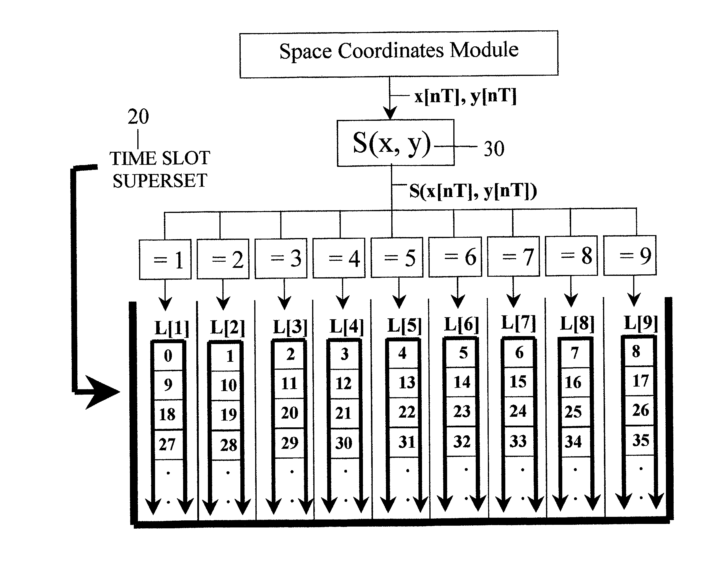
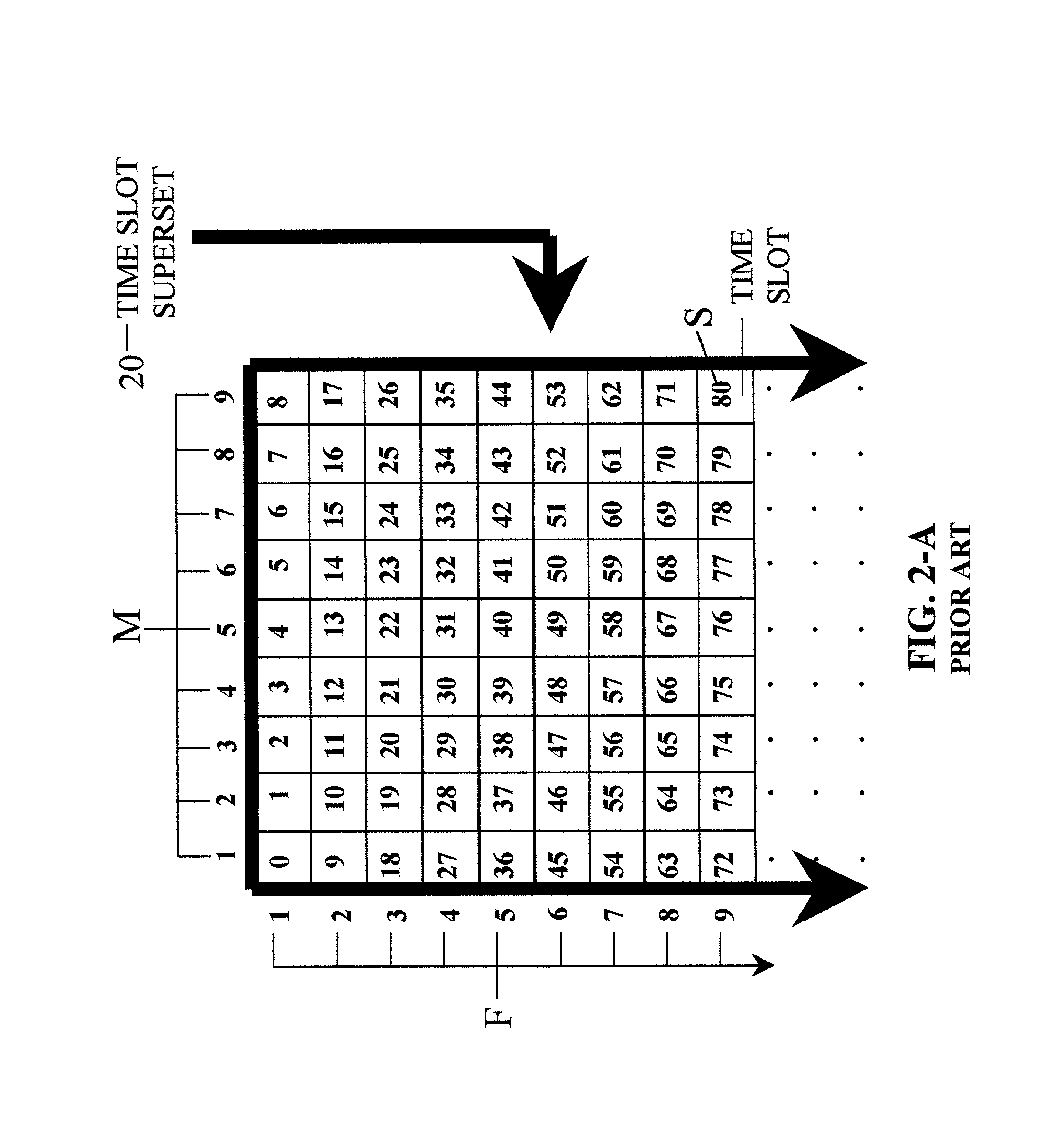
[0034]FIG. 2-A shows the first 80 time slots of a time slot superset 20 belonging to a common Time Division Multiple Access (TDMA) channel. A time slot is uniquely identified by its sequence number S. Alternatively, a time slot can be uniquely identified by the pair (M, F), where M is the time slot's circular sequence number (column number in FIG. 2-A), and F is the time slot's frame sequence number (row number in FIG. 2-A). A time frame is defined as a group of 9 consecutive time slots. In FIG. 2-A, each row of time slots is a different time frame.

[0035]The sequence number S and the circular sequence number M of a particular time slot are related by the following equation:

M=Modulo[S / 9]+1  (1)

M is a time slot sequence number that resets to 1 every 9 consecutive time slots. The maximum value of M is equal to the length (in slots) of the time frame. F is incremented every time M is reset to 1, which signifies the beginning of a new time frame. The sequence number S and the frame seque...


PUM


Abstract

A method for allocating a set of time slots belonging to a common time division multiple access (TDMA) channel to a network of transceiver nodes is provided. The method includes the steps of dividing the set of time slots into a plurality of time slot sub-sets; defining for each transceiver node a common function that assigns one time slot sub-set of the plurality of time slot sub-sets to each point in space, where each point in space is identified by a unique set of space coordinates; and performing the following steps for each one of the transceiver nodes: periodically identifying a set of space coordinates; and allocating to each transceiver node time slots belonging to the time slot sub-set assigned by the common function to the point in space identified by the periodically identified set of space coordinates. The method further includes the step of resolving time slot allocation conflicts occurring when at least two transceiver nodes are allocated time slots belonging to an identical time slot sub-set and the distance between the at least two transceiver nodes is less than a predetermined distance threshold. This step includes allocating to each one of the at least two transceiver nodes time slots belonging to a different time slot sub-set of the identical time slot sub-set. The periodically identified set of space coordinates corresponds to the current set of space coordinates for each one of the transceiver nodes.

Description

PRIORITY[0001]This application claims priority to a United States Provisional Patent Application filed on May 15, 2000 having U.S. Provisional Application Ser. No. 60 / 204,349, the contents of which are incorporated herein by reference.BACKGROUND OF THE INVENTION[0002]1. Field of the Invention[0003]The invention relates to the field of wireless communications, and specifically the invention relates to a method for dynamically allocating time slots of a common time division multiple access (TDMA) broadcast channel to a network of transceiver nodes.[0004]2. Description of the Prior Art[0005]A packet radio network consists of a number of geographically dispersed transceiver nodes that communicate with each other. Due to limited transmission power and the geographic distance that physically separates the nodes, the transmissions of a given node cannot be received by every other node in the network. Instead, the transmissions of a given node can be received only by the nodes located withi...

Claims


Application Information

Patent Timeline
IPC IPC(8): H04B7/212H04Q7/20H04B7/26H04Q11/04
CPCH04B7/2656H04Q11/0421H04Q2213/13098H04Q2213/13216H04Q2213/13392H04Q2213/13332H04Q2213/1334H04Q2213/13367H04Q2213/13292
Inventor AMOURIS, KONSTANTINOS
Owner WI LAN INC
Why Eureka
Try Eureka