Overlapping subarray architecture
a technology of subarrays and subarrays, applied in the manufacture of antenna arrays, electrical equipment, antennas, etc., can solve the problems of overlapping, increased cost, increased complexity of array architecture, and increased cost, so as to suppress the formation of grating lobes
- Summary
- Abstract
- Description
- Claims
- Application Information
AI Technical Summary
Benefits of technology
Problems solved by technology
Method used
Image
Examples
Embodiment Construction
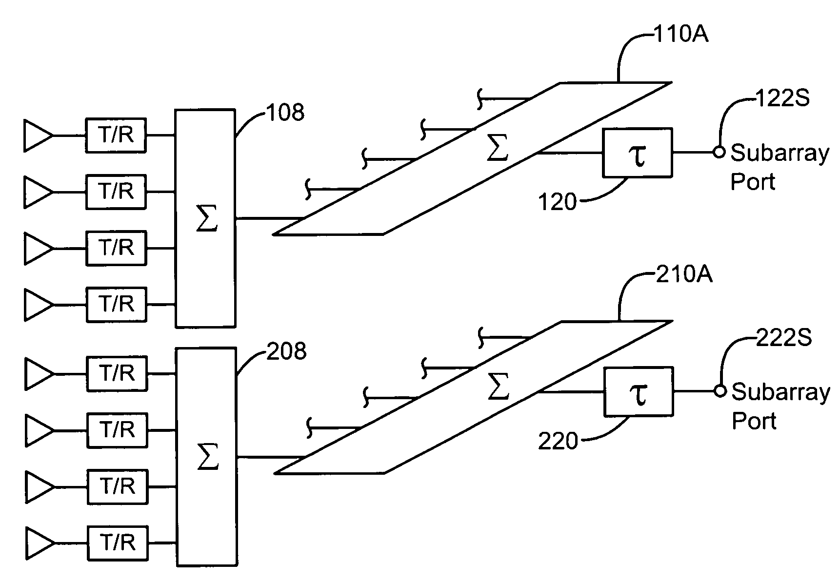
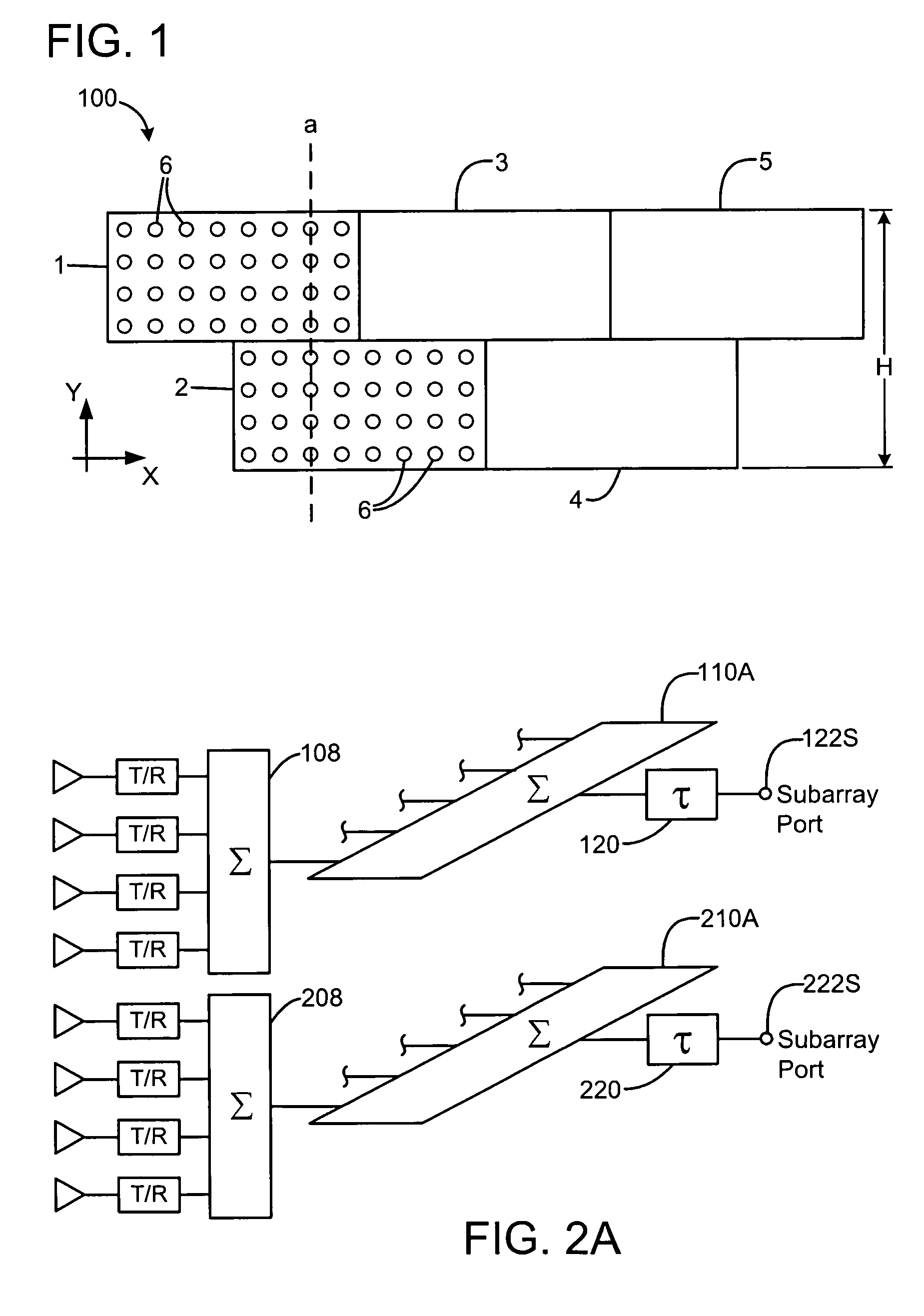
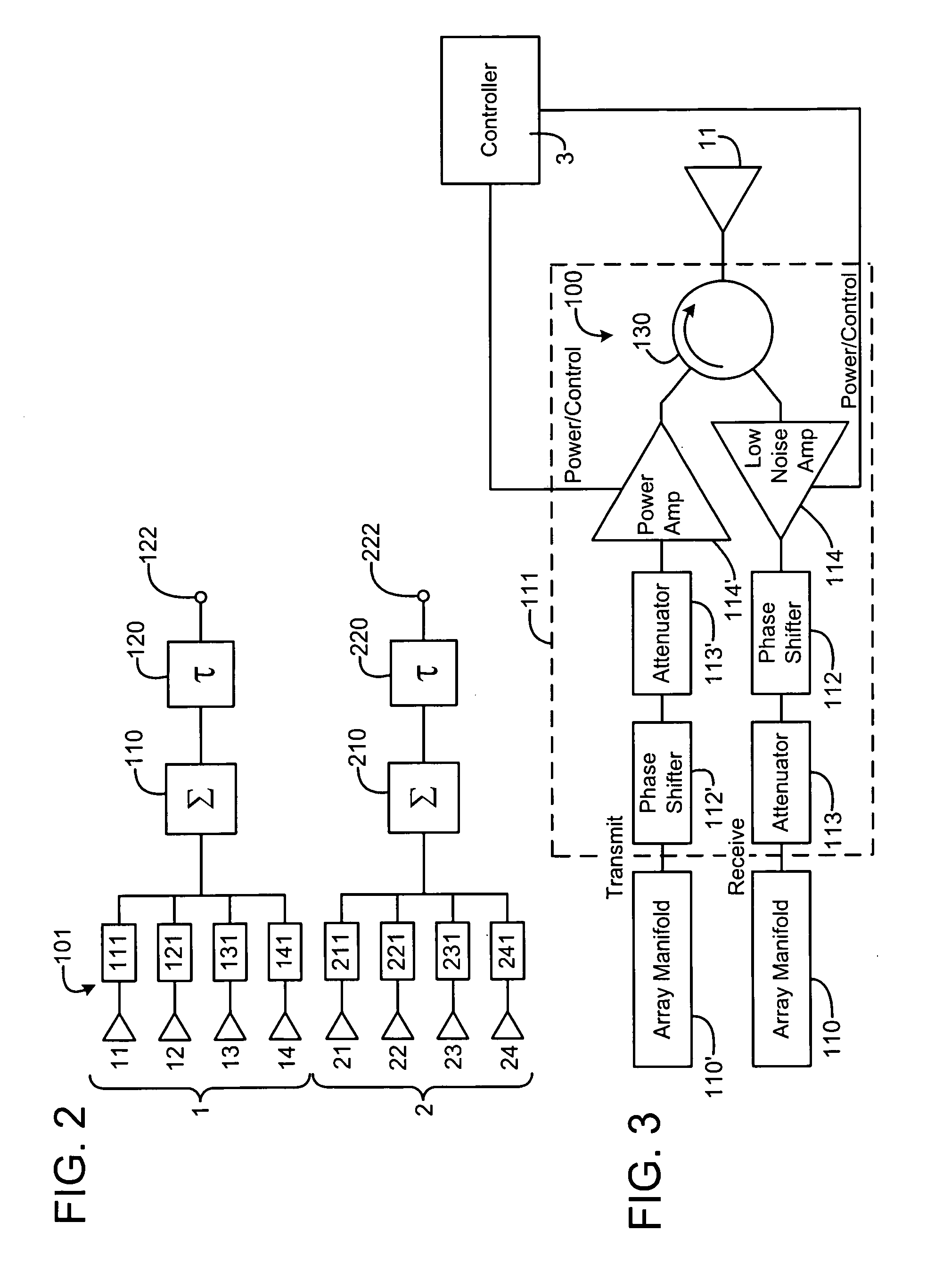
[0018]Exemplary embodiments of electronically scanned arrays, subarrays and array architectures are illustrated in FIGS. 1–8. In the following descriptions, the size, orientation and dimensions of the arrays, the size, orientation, dimensions and numbers of subarrays and subarray discrete radiative elements within those subarrays are used for convenience and by way of example only. The array radiative elements may be connected to transmit / receive modules (T / R modules). The exemplary embodiments discussed are suitable for horizontal and / or vertical extension in terms of the number of subarray discrete elements or radiative elements and in terms of the number, size, orientation, configuration and dimensions of the individual subarray elements, subarrays and the overall array.
[0019]Exemplary embodiments may provide a more readily calibrated and / or simplified array architecture for overlapped subarrays with off-frequency or limited multiple beam scan grating lobe locations and methods f...
PUM
 Abstract
Description
Claims
Application Information
 - Generate Ideas
- Intellectual Property
- Life Sciences
- Materials
- Tech Scout
- Unparalleled Data Quality
- Higher Quality Content
- 60% Fewer Hallucinations
Browse by: Latest US Patents, China's latest patents, Technical Efficacy Thesaurus, Application Domain, Technology Topic, Popular Technical Reports.
© 2025 PatSnap. All rights reserved.Legal|Privacy policy|Modern Slavery Act Transparency Statement|Sitemap|About US| Contact US: help@patsnap.com


