
Drink dispensing system

a technology of a dispensing system and a bottle, which is applied in the direction of domestic cooling devices, lighting and heating devices, instruments, etc., can solve the problems of excessive pressure drop, inconvenient dispensing, and insufficient insulation of the fluid in the tube,

Inactive Publication Date: 2006-07-25
MCCANNS ENG & MFG CO
View PDF50 Cites 20 Cited by
  • Summary
  • Abstract
  • Description
  • Claims
  • Application Information

AI Technical Summary

Problems solved by technology

However, the ingredients are frequently stored at a distance from the dispensing equipment.
Because of limited space, fluids in these tubes are not insulated.
The length of tubing and the circuitous coiling of the tubing in such cold plates can create a significant pressure drop in the flow therethrough.
An excessive pressure drop can adversely affect the operation of the system during busy times as a certain level of pressure is demanded at the dispensers to insure adequate throughput.
At the same time, excessive carbonation resulting from high pressure in the carbonator can create a foaming problem.
Excessive pressure drop through successive coil circuits can, therefore, require substantial pressure prior to the cooling process to achieve the required minimum pressure at the faucet.
If carbon dioxide is introduced prior to the pressure drop under such conditions, excessive carbonation can result.
These cold plates are much heavier in design than earlier such devices.
Mechanical refrigeration is more expensive and requires more frequent service.
When mechanical refrigeration systems fail, the system must be shut down pending repair rather than, again, just adding more ice.
Mechanically refrigerated cooling systems are principally employed with very high volume systems at substantial cost.
However, the most problematic is the maintenance of low temperature within the beverage to be dispensed in order that stable carbonation can be maintained in the drink when dispensed.
Even so, the low volume casual drink usage remains problematic in cold plate systems.

Method used


Image

  • Drink dispensing system
  • Drink dispensing system
  • Drink dispensing system

Examples


Embodiment Construction

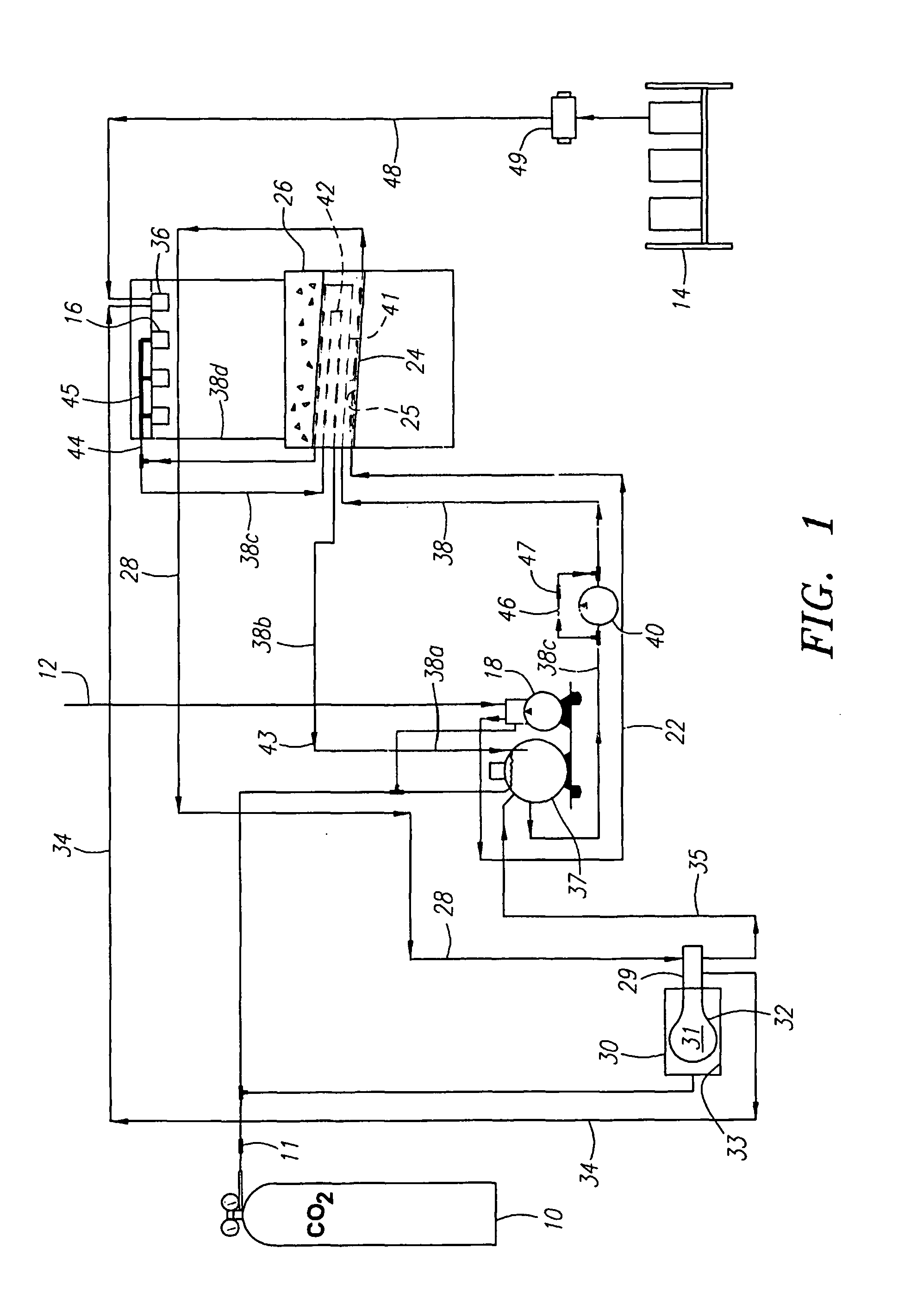
[0029]Turning in detail to the figures, FIG. 1 illustrates a single dispensing station for both carbonated and noncarbonated beverages. The drink dispensing system is shown to include a source of carbon dioxide 10 protected by a check valve 11, a water inlet 12 and a source of syrups 14. From these, a plurality of carbonated and noncarbonated flavored drinks can be dispensed through the dispensers 16.

[0030]Water enters from the water inlet 12 to a supply pump 18 where the pressure is raised. The incoming water from the supply pump 18 may be directed through a water line 22 to a cold plate 24 if the water is to be chilled before carbonation. The cold plate 24 forms the bottom of an ice storage bin 26 and has conventional coils 25 therethrough to receive the incoming water from the water line 22. The water from the coils 25 of the cold plate 24 is then directed through a cold water line 28 to a water pressure booster valve 29 for selected distribution. Carbon dioxide, also under press...


PUM


Abstract

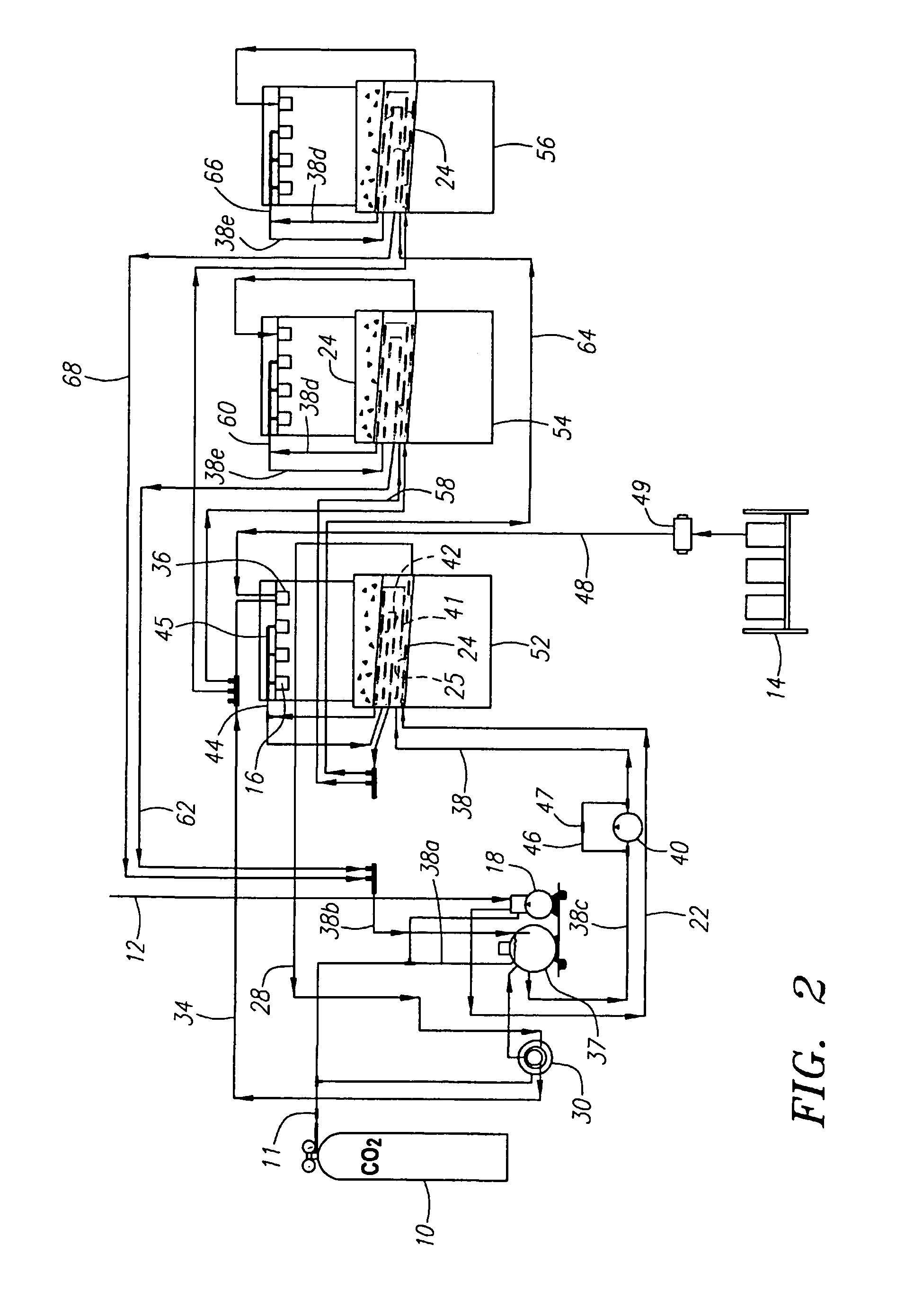
A drink dispensing system having sets of faucet dispensers, ice storage bins adjacent to the sets of faucet dispensers, respectively, a common carbonator and circulation pumps associated with fluid circuits provide circulating flow through cold plates defining bottoms to the ice storage bins. Flow may be in parallel or in series to each of the separate stations. The circulating system is illustrated to be for the carbonated water supply while noncirculating supply systems provide noncarbonated water and syrup to the dispensing stations. Circulating systems for bar guns using a cold plate are also disclosed.

Description

REFERENCE TO RELATED CASES[0001]This is a divisional application of U.S. patent application Ser. No. 10 / 237,165, filed Sep. 6, 2002, now U.S. Pat. No. 6,725,687 the disclosure of which is incorporated herein by reference.BACKGROUND OF THE INVENTION[0002]The field of the present invention is systems for dispensing carbonated beverages and the cooling of the supplied beverages.[0003]Commercial establishments with drink dispensing systems employ a variety of mechanisms to create and dispense carbonated and noncarbonated beverages. Such systems generally associated with what may be termed fountain service typically generate the carbonated water from carbon dioxide and service water. The beverage ingredients, water, carbonated water and syrups, are then mixed at faucets upon demand. Mixing spouts associated with valves forming the faucets are disclosed in U.S. Pat. No. 4,928,854 and U.S. Pat. No. 6,401,981, the disclosures of which are incorporated herein by reference. In commercial syst...

Claims


Application Information

Patent Timeline
Patent Type & Authority Patents(United States)
IPC IPC(8): B67D5/62B67D7/80B67D1/00B67D1/04B67D1/08
CPCB67D1/0021B67D1/0064B67D1/0857B67D1/0406B67D1/0084
Inventor MCCANN, GERALD P.VERLEY, DONALD J.
Owner MCCANNS ENG & MFG CO
Learn More