
Automated connections of computer-aided design components

a technology of computer-aided design and components, applied in the direction of total factory control, programme control, instruments, etc., can solve the problems of parts becoming incompatible with respect, and achieve the effect of improving efficiency, flexibility, and functionality of a computerized modeling system

Inactive Publication Date: 2006-07-18
DASSAULT SYST SOLIDWORKS CORP
View PDF9 Cites 148 Cited by
  • Summary
  • Abstract
  • Description
  • Claims
  • Application Information

AI Technical Summary

Benefits of technology

[0020]The details of one or more embodiments of the invention are set forth in the accompanying drawings and the description below. Implementations can include one or more of the following advantages. An automated connection mechanism automates the process of finding standard part models in a database and incorporating the standard parts in an assembly model, thereby encouraging the use of standard industry parts that may be contained in a commercially available database. An automated connection mechanism notifies the design engineer when a modification of the assembly model causes a part to become incompatible with respect to a feature within the assembly. The design engineer then may command the system to perform another automated search for an appropriate part in the database. Furthermore, the automated connection mechanism may be extendible, allowing a design engineer to expand the database as needed. Efficiency, flexibility, and functionality of a computerized modeling system may be enhanced. Other features, objects, and advantages of the invention will be apparent from the description and drawings, and from the claims.

Problems solved by technology

An automated connection mechanism notifies the design engineer when a modification of the assembly model causes a part to become incompatible with respect to a feature within the assembly.

Method used


Image

  • Automated connections of computer-aided design components
  • Automated connections of computer-aided design components
  • Automated connections of computer-aided design components

Examples


Embodiment Construction

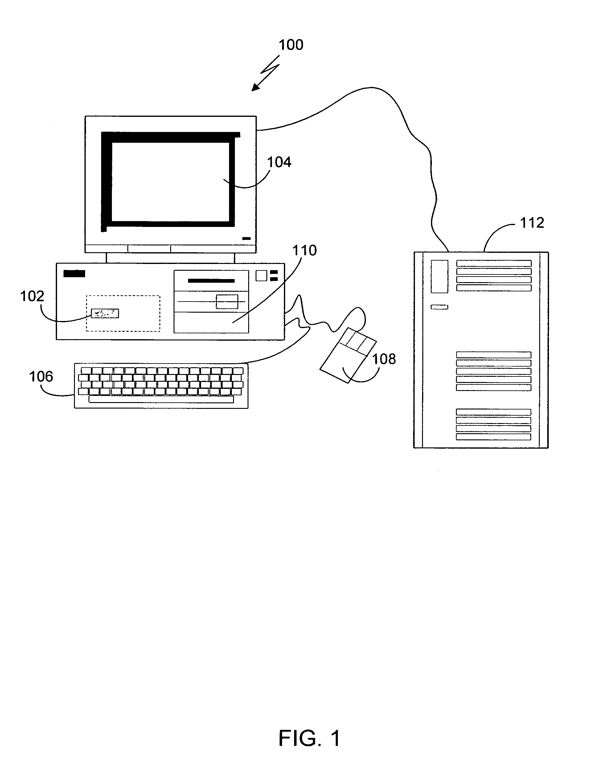
[0037]FIG. 1 shows a computerized modeling system 100 that includes a CPU 102, a CRT 104, a keyboard input device 106, a mouse input device 108, and a storage device 110. The CPU 102, CRT 104, keyboard 106, mouse 108, and storage device 110 can include commonly available computer hardware devices such as a Pentium-based processor. The mouse 108 has conventional left and right buttons that the user may press to issue a command to a software program being executed by the CPU 102. Other appropriate computer hardware platforms are suitable as will become apparent from the discussion that follows. Such computer hardware platforms are preferably capable of operating the Microsoft Window NT, Windows 95, Windows 98, Windows 2000, or UNIX operating systems.

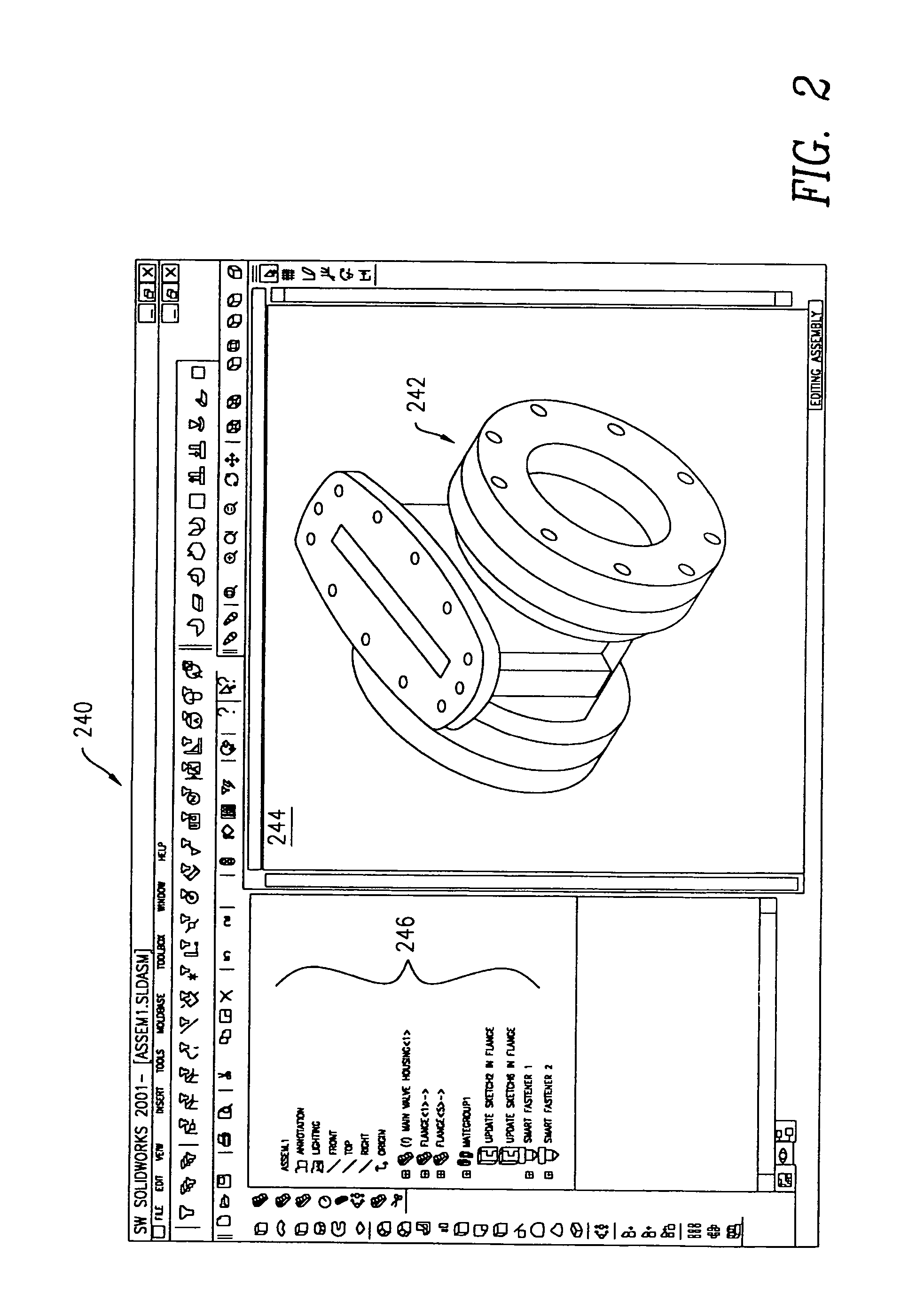
[0038]Computer-aided design software is stored on the storage device 110 and is loaded into and executed by the CPU 102. The computer-aided design software allows the user to create and modify a 3D model and implements aspects of the inven...


PUM


Abstract

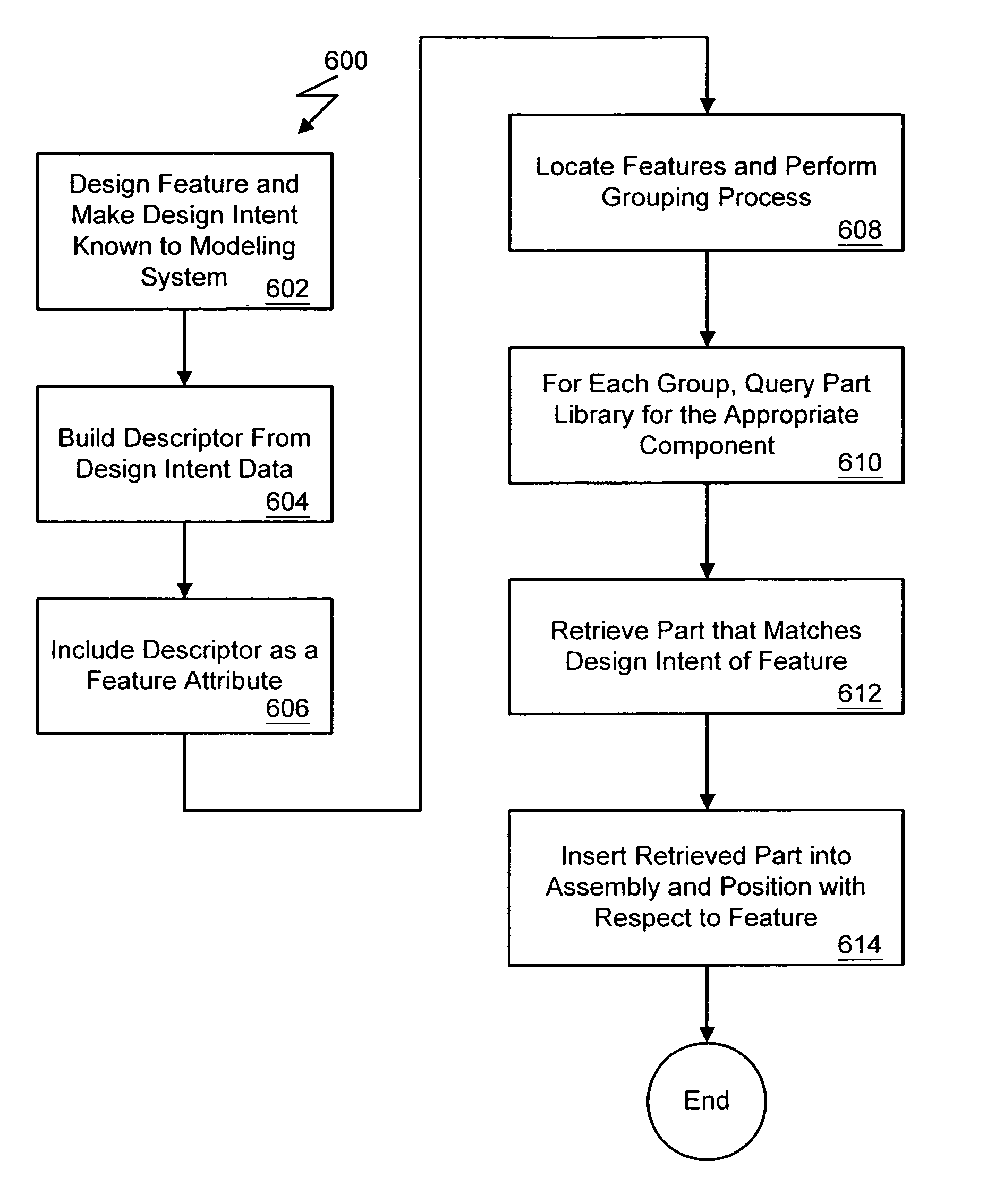
Construction of a model using a computer aided design system includes constructing a feature in a three dimensional model based on data input by a user. Following construction of the feature, a part configured to compatibly couple with the feature is automatically identified based on design attributes of the feature. The part can be selected from a parts library that includes data representing parts and their geometric characteristics. The part also may be automatically generated based on a part model in a parts library. The part generation can include querying a database storing the part library to retrieve a part model, and then generating an instance of the part model based on design attributes of the feature so as to ensure coupling compatibility with the feature.

Description

BACKGROUND OF THE INVENTION[0001]Computer-aided design (CAD) software allows a user to construct and manipulate complex three-dimensional (3D) models of assembly designs. A number of different modeling techniques can be used to create a model of an assembly. These techniques include solid modeling, wire-frame modeling, and surface modeling. Solid modeling techniques provide for topological 3D models formed from a collection of interconnected edges and faces. Geometrically, a 3D solid model is a collection of trimmed surfaces. The trimmed surfaces correspond to the topological faces bounded by the edges. Wire-frame modeling techniques, on the other hand, can be used to represent a model as a simple line drawing. Surface modeling can be used to represent a model's exterior surfaces. CAD systems may combine these, and other, modeling techniques. For example, parametric modeling techniques can be used to define various parameters for different components of a model. Solid modeling and p...

Claims


Application Information

Patent Timeline
Patent Type & Authority Patents(United States)
IPC IPC(8): G06F17/50G06T17/00G05B19/418G06T19/20
CPCG05B19/41805G06T19/20G06F17/50G05B2219/31064G06T2219/2004G06F2217/02G06F2111/20G06F30/00Y02P90/02
Inventor HALLER, KIRK D.AMADON, GARY W.NOFTLE, ROBERT D.CORCORAN, DAVID J.
Owner DASSAULT SYST SOLIDWORKS CORP
Learn More