
Process for generating a variable frequency signal, for instance for spreading the spectrum of a clock signal, and device therefor

a technology of variable frequency and clock signal, which is applied in the direction of pulse automatic control, angle demodulation by phase difference detection, electrical apparatus, etc., can solve the problem of uncompromised operation of the entire system, and achieve the effect of achieving the final resul

Active Publication Date: 2006-07-18
STMICROELECTRONICS SRL
View PDF16 Cites 40 Cited by
  • Summary
  • Abstract
  • Description
  • Claims
  • Application Information

AI Technical Summary

Benefits of technology

[0010]The object of this invention is the realization of a further improvement in the previously described spread spectrum technique, both with regards to the efficiency of the final result that is achieved and in respect of the possibility of realizing adaptable and technologically simple devices, avoiding the need to resort to memories and / or critical analogue components.

Problems solved by technology

Only if the variations in clock frequency are sufficiently slow does the functioning of the entire system remain uncompromised.

Method used


Image

  • Process for generating a variable frequency signal, for instance for spreading the spectrum of a clock signal, and device therefor
  • Process for generating a variable frequency signal, for instance for spreading the spectrum of a clock signal, and device therefor
  • Process for generating a variable frequency signal, for instance for spreading the spectrum of a clock signal, and device therefor

Examples


Embodiment Construction

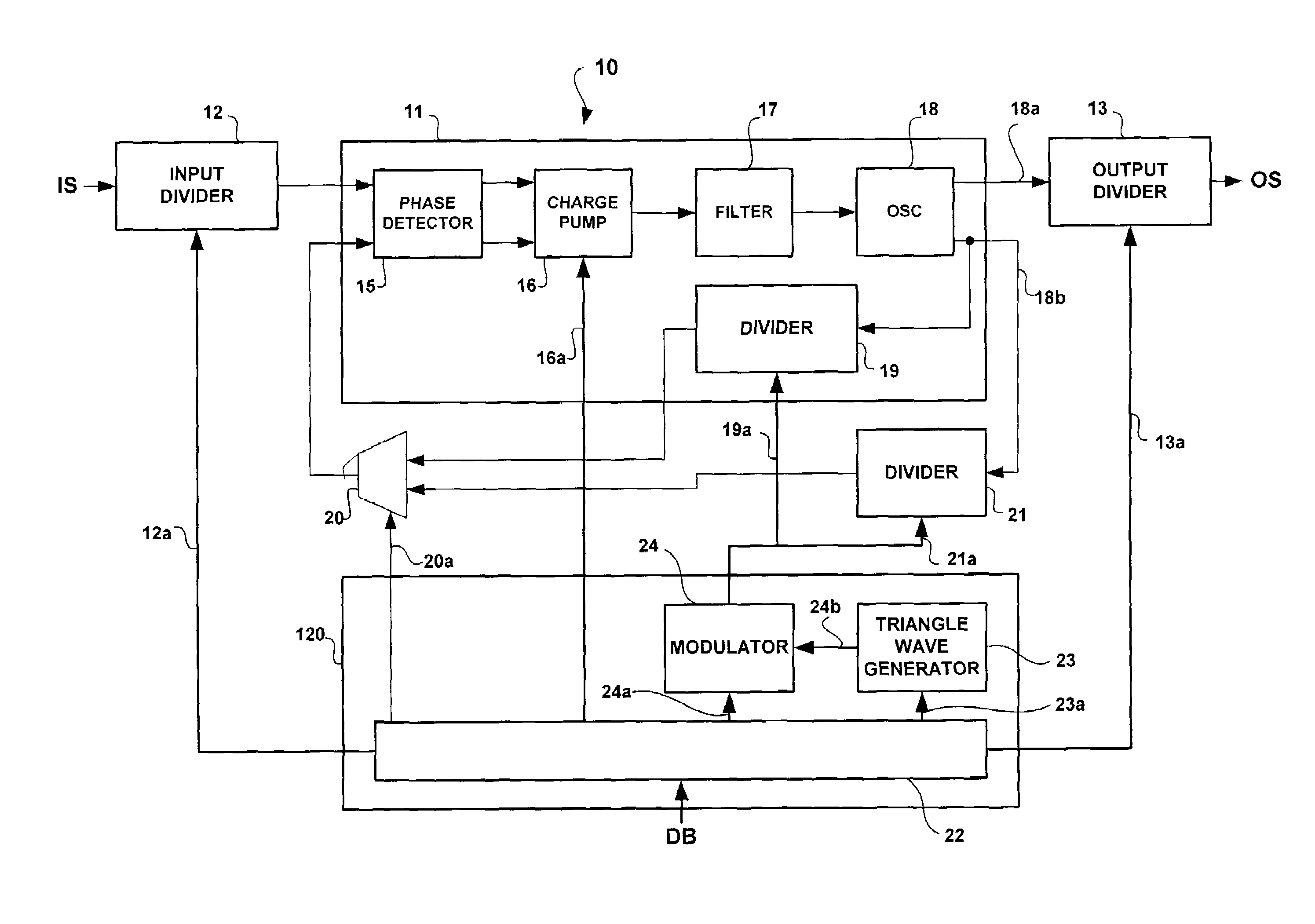
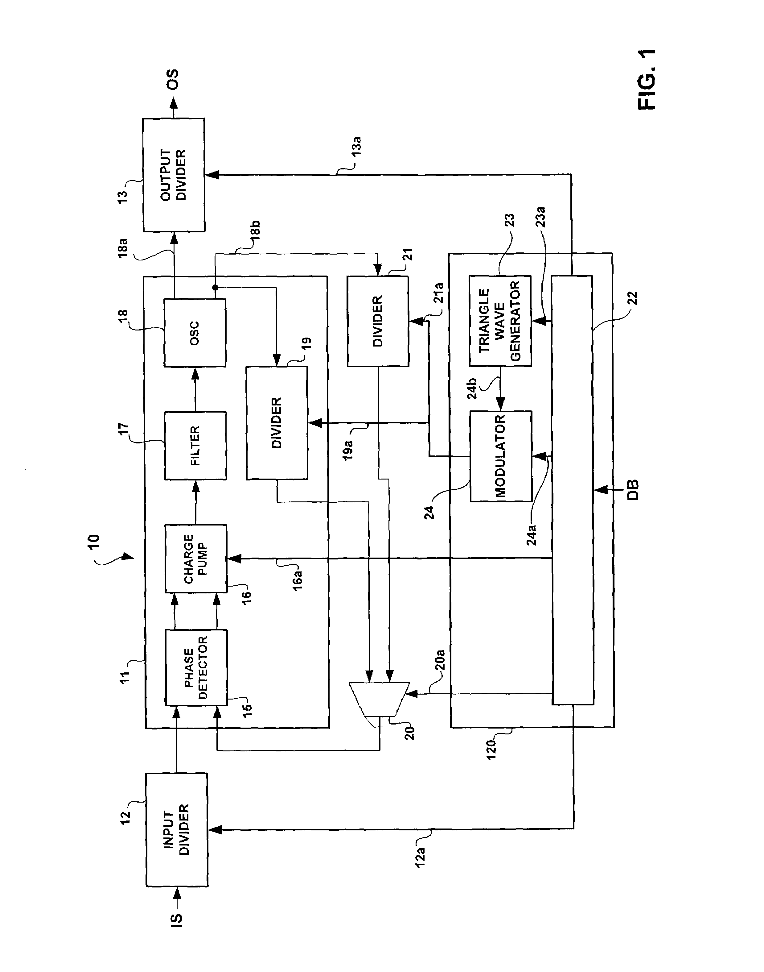
[0017]In the layout shown in FIG. 1, numerical reference 10 indicates an entire circuit capable of performing the function of an SSCG (Spread Spectrum Clock Generator) or “dithered PLL”, that is the generation, starting from an input signal IS consisting of a constant frequency clock signal, of an output signal OS consisting of a “dithered” square-wave signal, that is to say with a frequency modulation that gives rise to a spreading out of the relative power spectrum.

[0018]The core of circuit 10 consists of a PLL 11 to which two divider circuits 12 and 13 are associated, in input and output respectively, as well as a control block, indicated in its entirety as reference 14.

[0019]According to a commonly known architecture, the PLL includes:[0020]a phase detector 15 capable of detecting the phase shift between the first input signal, consisting of the divider circuit 12 output signal in the example illustrated herein, and a second signal originating from the feedback of the PLL, which...


PUM


Abstract

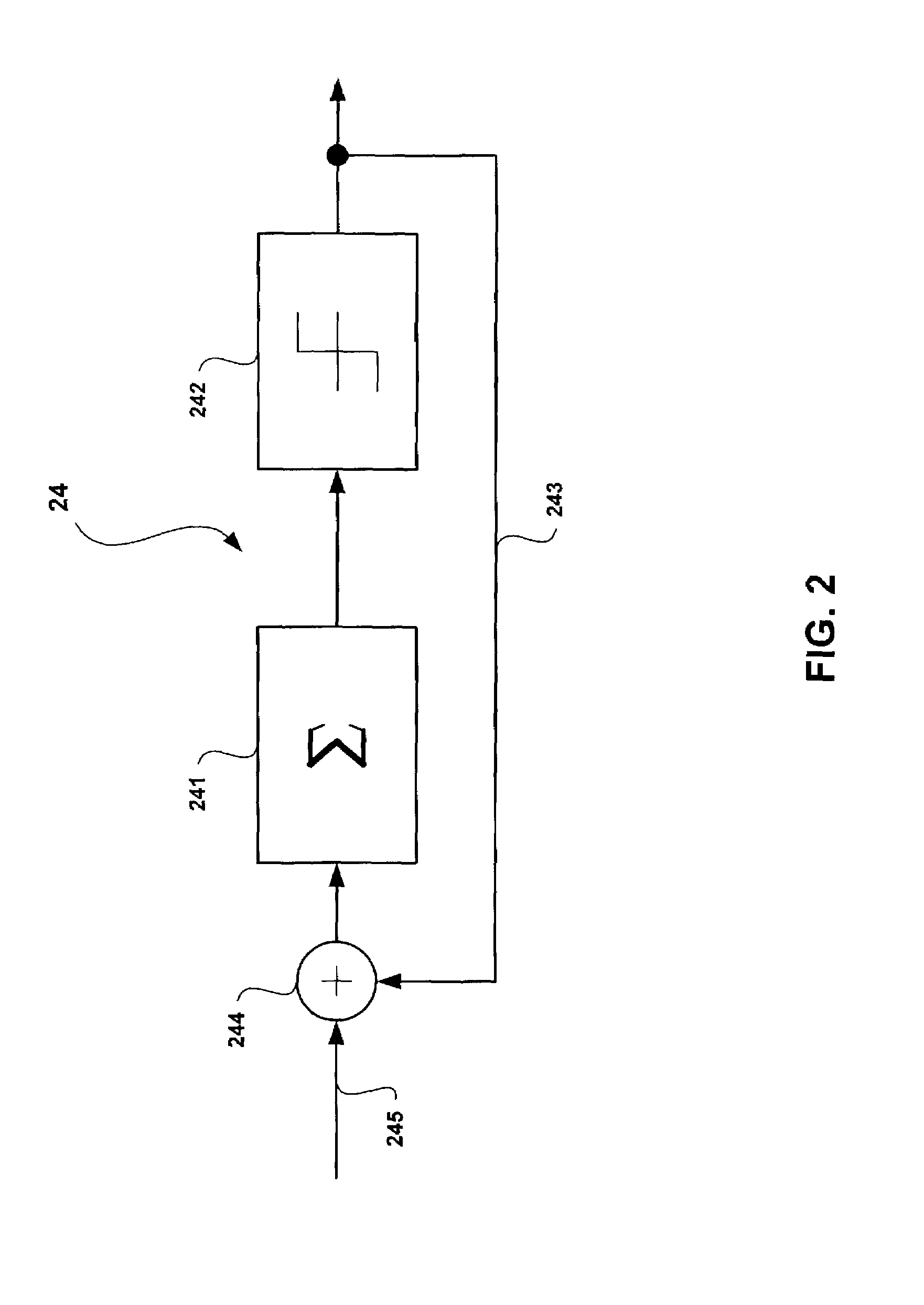
The use of a PLL including a phase detector responsive to the phase difference between an input signal and a feedback signal and which pilots an oscillator in function of this difference, is envisaged. The PLL also includes a feedback path that is responsive to the signal generated by the oscillator and which generates said feedback signal via at least one divider with a variable division ratio. The division ratio of said divider is modulated via a sigma-delta modulator, the input of which is fed with a triangular-wave modulating signal. The preferred application is that of a spread spectrum clock generator (SSCG) for digital electronic systems.

Description

FIELD OF THE INVENTION[0001]The present invention refers to techniques that allow a variable frequency signal to be generated for use, for example, in broadening the spectrum (spread spectrum) of a square-wave clock signal generated via a PLL (Phase Locked Loop).BACKGROUND OF THE INVENTION[0002]All electronic devices emit more or less strong electromagnetic radiation during normal operation, with a spectral bandwidths ranging from very narrow bands to bands that cover wide zones of the electromagnetic spectrum. One consequence of these emissions can be evaluated in terms of “noise” or “interference” on other electronic equipment. The powers brought into play depend on the characteristics of the device in question.[0003]The evolution of electronic technologies over recent years has certainly brought about an increase in radiated powers, as can be witnessed, for example, by the wide-scale diffusion of mobile phones and the tendency towards ever-increasing clock frequencies in digital ...

Claims


Application Information

Patent Timeline
Patent Type & Authority Patents(United States)
IPC IPC(8): H03D3/24H03L7/089H03L7/197
CPCH03L7/197H03L7/0898
Inventor CASTIGLIONE, CORRADOSCIPIONI, MASSIMOROMANI, CARLO ALBERTO
Owner STMICROELECTRONICS SRL
Learn More