
Color image processing apparatus and color image processing system using the apparatus

a technology of color image processing and color image, applied in the direction of colour separation/tonal correction, digital output to print units, instruments, etc., to achieve the effect of low cos

Inactive Publication Date: 2006-07-18
FUJIFILM BUSINESS INNOVATION CORP
View PDF20 Cites 21 Cited by
  • Summary
  • Abstract
  • Description
  • Claims
  • Application Information

AI Technical Summary

Benefits of technology

The invention provides a color image processing system that can create precise color reproductions at a low cost and in a variety of output units. The system includes a color proof generation section that converts original data into raster data and expands it. The raster data is then transferred to the output unit, which can be a printer or other output device. The system can be connected through a network, making it easy to use in different departments and with different operators. The system can also be used as a color image processing apparatus, providing precise color reproduction in any department. The system can be connected to a network and used as a color image processing apparatus. The invention also provides a method for calibrating the color reproduction in the output unit. Overall, the invention provides a cost-effective and efficient solution for creating precise color reproductions.

Problems solved by technology

Thus, at the transfer destination, an expensive apparatus for performing color conversion processing and expanding original data into raster data is not required and a skilled operator is not needed either and the color proof reproduced in precise color can be provided.

Method used


Image

  • Color image processing apparatus and color image processing system using the apparatus
  • Color image processing apparatus and color image processing system using the apparatus
  • Color image processing apparatus and color image processing system using the apparatus

Examples


first embodiment

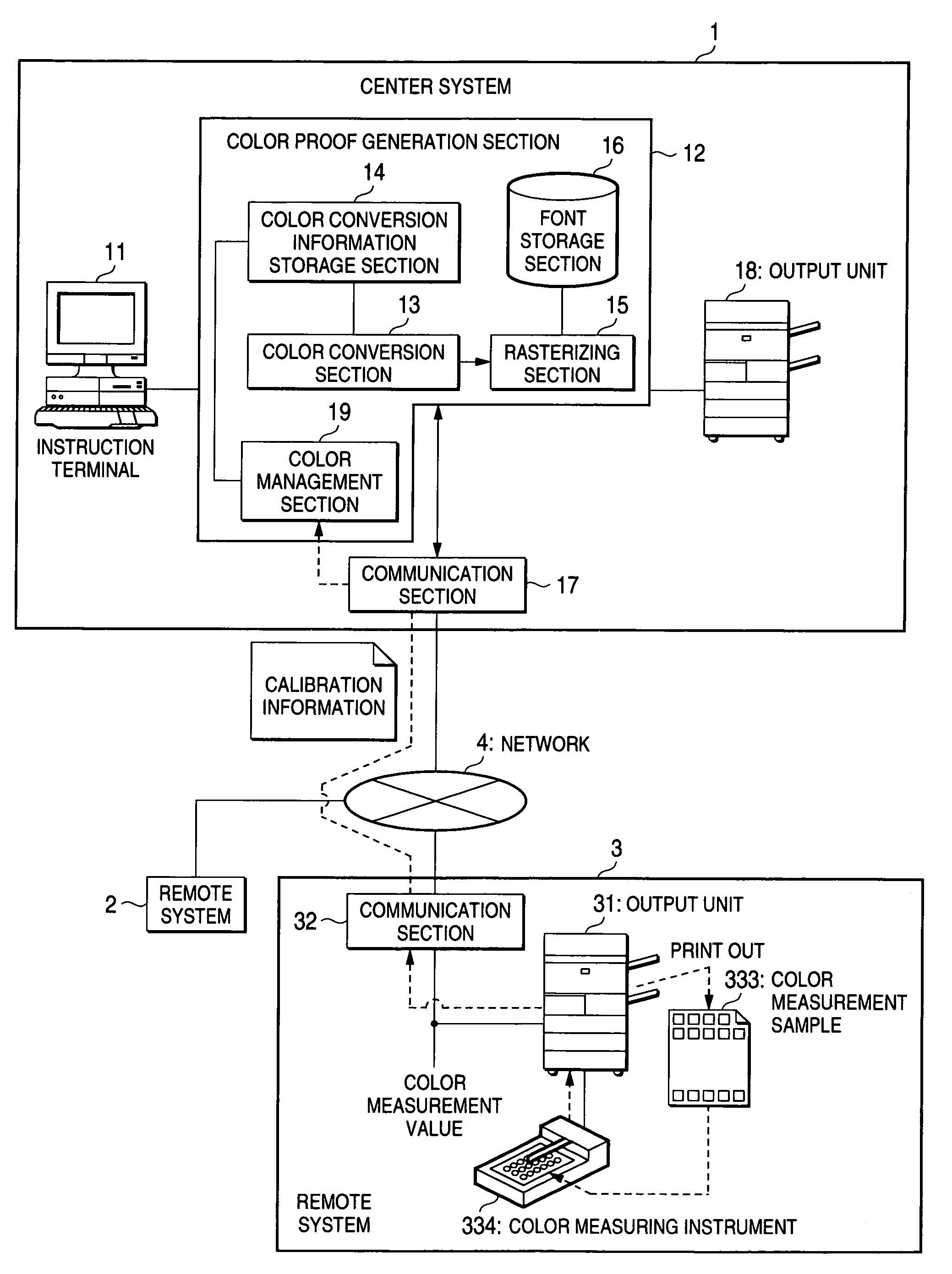
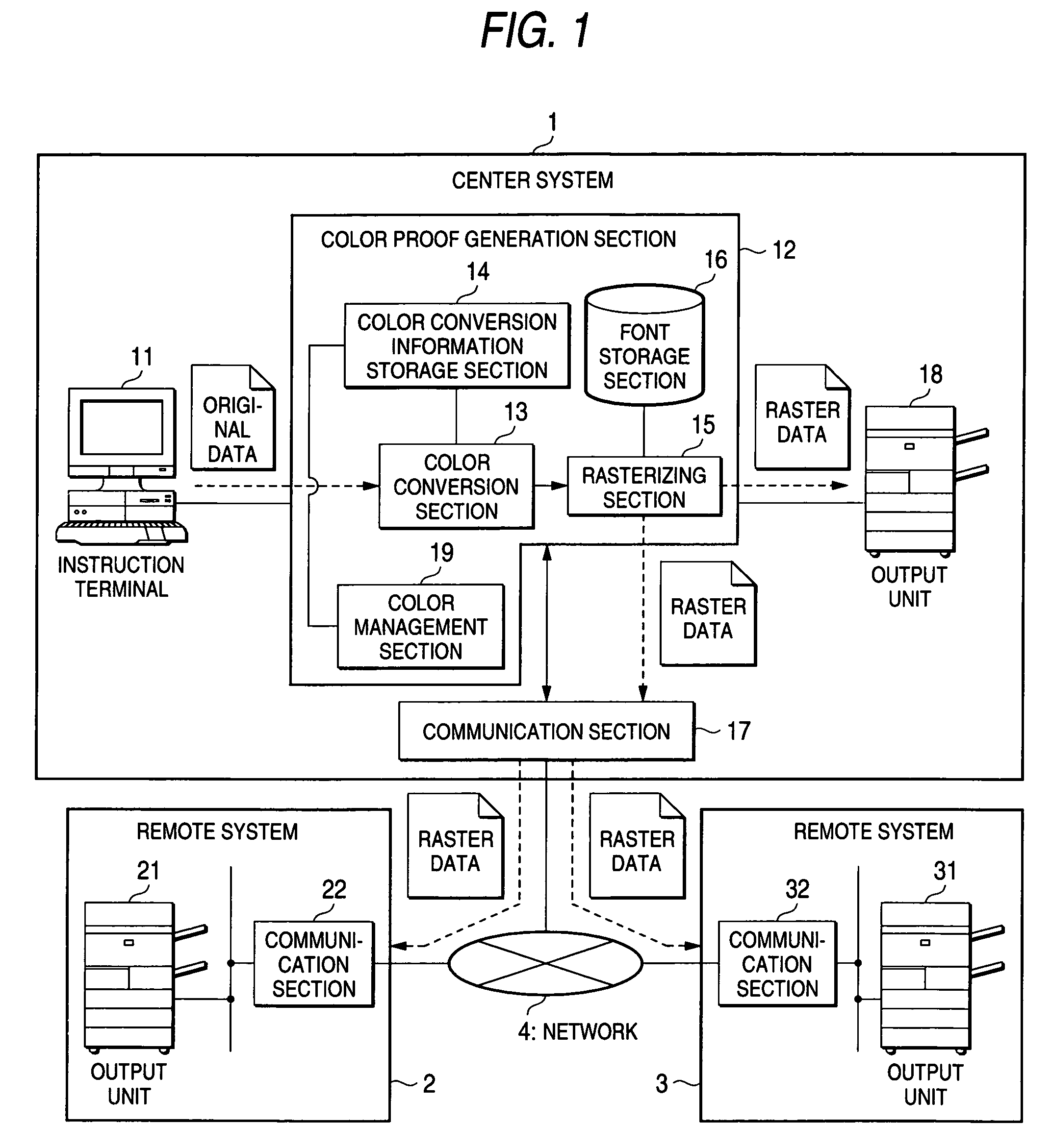
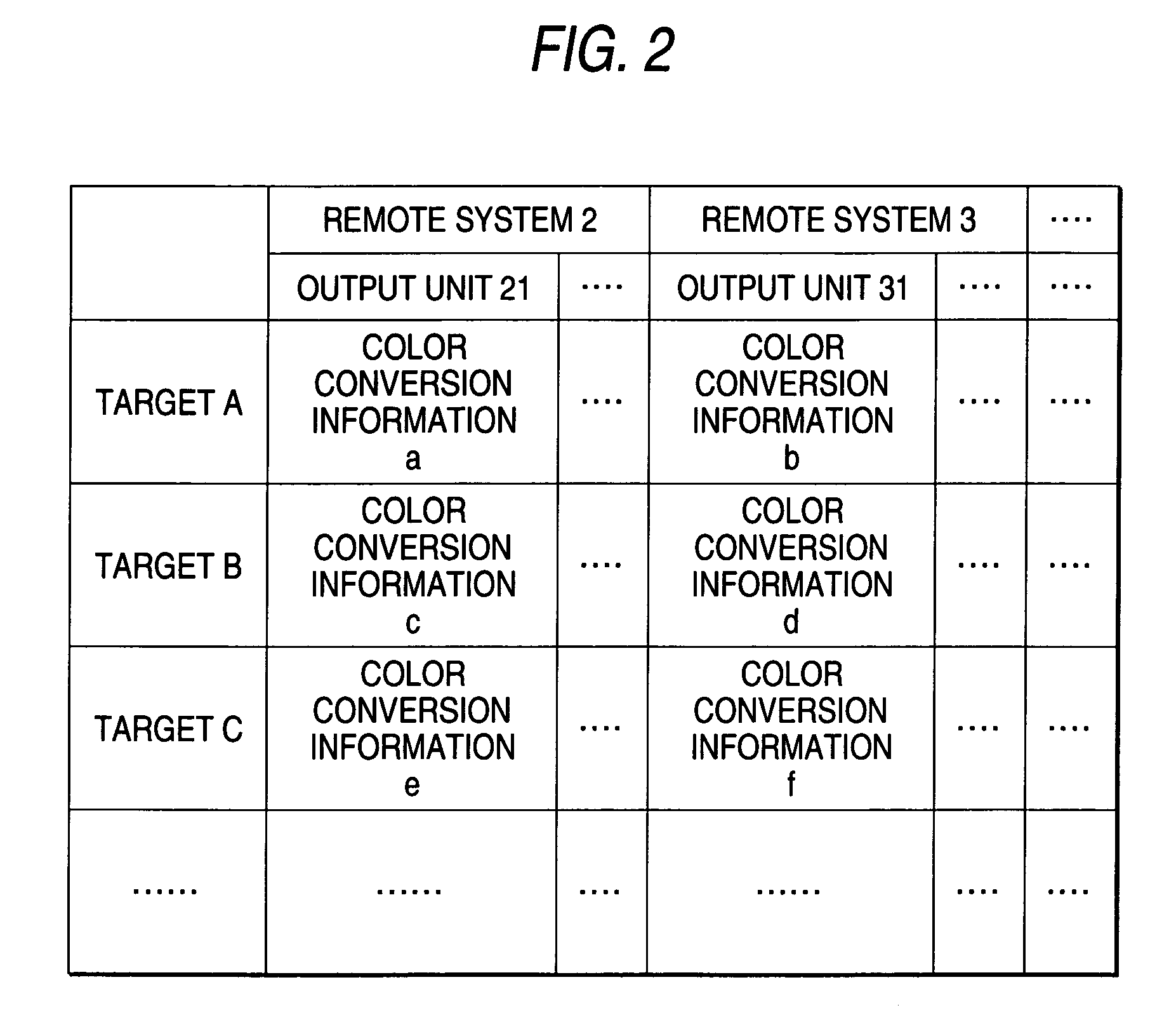
[0051]FIG. 1 is a block diagram to show a first embodiment of a color image processing system using a color image processing apparatus according to the invention. In the figure, numeral 1 denotes a center system (color image processing apparatus), numerals 2 and 3 denote remote systems, numeral 4 denotes a network, numeral 11 denotes an instruction terminal, numeral 12 denotes a color proof generation section, numeral 13 denotes a color conversion section, numeral 14 denotes a color conversion information storage section, numeral 15 denotes a rasterizing section, numeral 16 denotes a font storage section, numeral 19 denotes a color management section, numerals 17, 22, and 32 denote communication sections, and numerals 18, 21, and 31 denote output units. In the color image processing system shown in FIG. 1, the center system 1 and the remote systems 2 and 3 are connected by the network 4. For example, the color image processing system can be constructed by installing the center syste...

second embodiment

[0092]FIG. 6 is a block diagram to show a second embodiment of a color image processing system using a color image processing apparatus according to the invention. Parts similar to those previously described with reference to FIG. 1 are denoted by the same reference numerals in FIG. 6 and will not be discussed again. In FIG. 6, numeral 601 denotes a center server (color image processing apparatus), numerals 602, 603, and 605 denote client systems, numeral 618 denotes a charging section, numeral 651 denotes an output unit, numeral 652 denotes a communication section, and numeral 653 denotes an instruction terminal. In the color image processing system shown in FIG. 6, the center server 601 and the client systems 602, 603, and 605 are connected by a network 4. For example, the color image processing system can be constructed by installing the client systems 602 and 603 in an orderer and a printing company and the client system 604 in a production company. Of course, the number of the ...


PUM


Abstract

When an output unit to produce output is specified through an instruction terminal 11 and original data is input to a color proof generation section 12, a color conversion section 13 acquires a color conversion parameter corresponding to the specified output unit from a color conversion information storage section 14 and performs color conversion processing for the original data so as to accomplish precise color reproduction in the specified output unit. A rasterizing section 15 expands the original data after undergoing the color conversion processing into raster data while using an enormous number of fonts in a font storage section 16. The raster data provided by the rasterizing section 15 is transmitted from a communication section 17 through a network 4 to the specified output unit. If a remote system 2 or 3, which receives the raster data, prints out on output unit 21 or 31, a color proof whose color is reproduced precisely can be provided.

Description

BACKGROUND OF THE INVENTION[0001]1. Filed of the Invention[0002]This invention relates to a color image processing apparatus for causing an output unit connected via a network to output a color image and a color image processing system using such the color image processing apparatus.[0003]2. Description of the Related Art[0004]In case of producing printed matter, steps of planning, design, production, proofreading, plate-making, printing plate, and final printing are executed. Various peoples and enterprises are involved in the steps. In recent years, a mechanized system has been used in the process from plate-making to printing. The steps of planning, design, and production are also being mechanized with widespread use of personal computers, etc. However, under the present circumstances, particularly the proofreading relies on the manpower.[0005]In the proofreading work, the whole design, placement of each of characters and images, color and font of each of parts, and the like are ...

Claims


Application Information

Patent Timeline
Patent Type & Authority Patents(United States)
IPC IPC(8): G06K15/00H04N1/00H04N1/40H04N1/60
CPCG06K15/00H04N1/40006H04N1/6011H04N1/6055H04N1/32529G06K2215/0082G06K2215/0094H04N1/00204H04N2201/0082
Inventor KIYOSU, TETUSYASUZUKI, SATOSHIKURAMOTO, HIROFUMIKATOH, NOBUHISAKAWASAKI, EISUKEKODAMA, MARIISHIZUKA, RYUICHINISHIDE, YASUSHIKAWAHARA, KOUICHI
Owner FUJIFILM BUSINESS INNOVATION CORP
Learn More