
Pulse Cam

a technology of pulse cams and pulses, applied in the field of pulse cams, can solve the problems of limited field of application, limited practical type of devices, and limited devices in the majority of these devices

Inactive Publication Date: 2006-07-18
CROSBY ADVANCE MEDICAL SYST
View PDF11 Cites 4 Cited by
  • Summary
  • Abstract
  • Description
  • Claims
  • Application Information

AI Technical Summary

Benefits of technology

[0009]A primary objective of the invention is to provide a tool for therapy treatments that does not have to be in contact with the skin surface of a patient, that does not have the tissue depth penetration limitations of electromagnetic sources and vibratory devices.
[0014]A sixth objective of the invention is to provide a tool for therapy treatments that reduces and eliminates patient injury risks, and allows for most any body tissue to be easily reached and treated by the tool.
[0015]A seventh objective of the invention is to provide a tool for therapy treatments that reduces and potentially eliminates fatigue and malaise injuries to the tool operator or previously known devices.
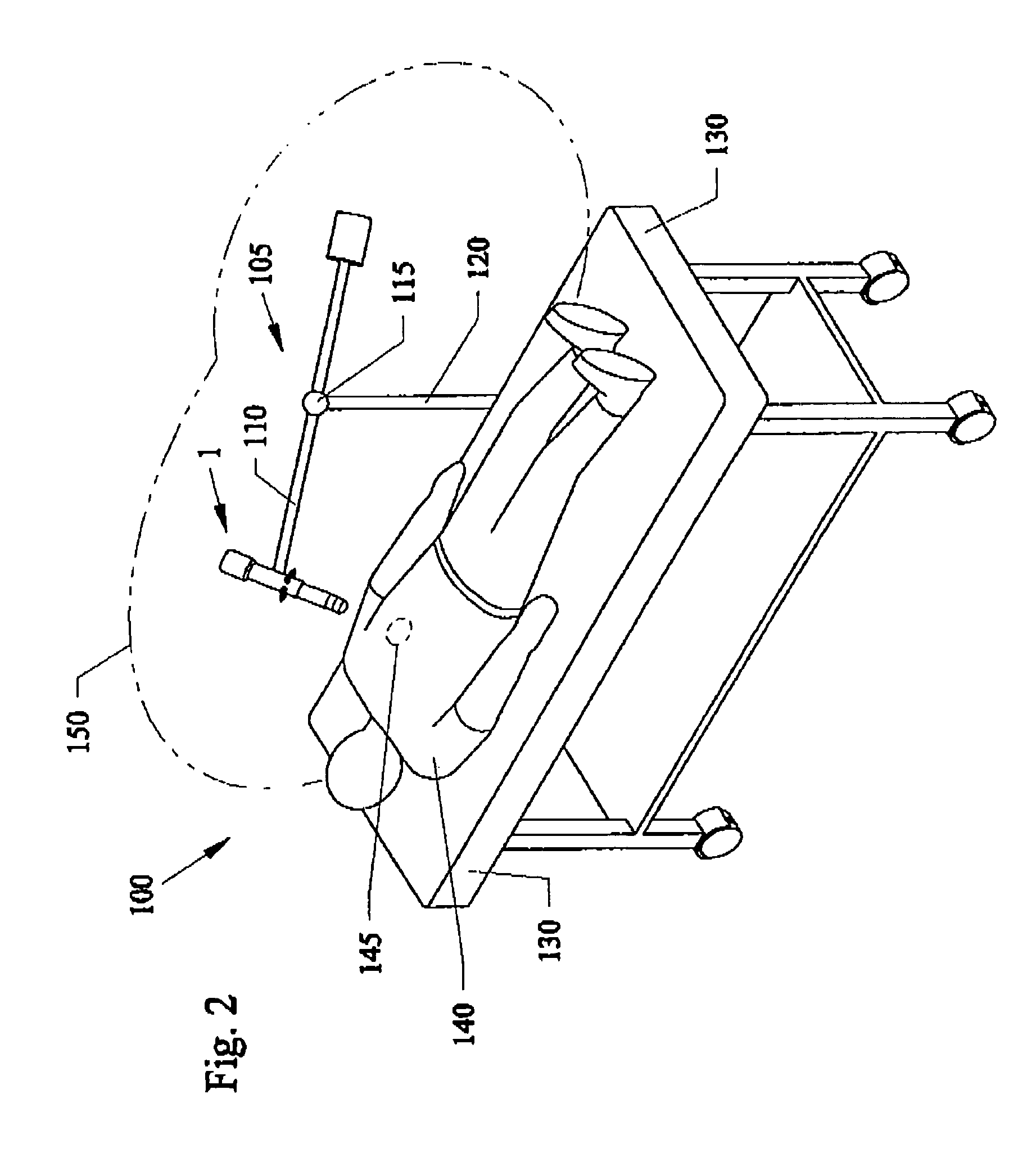
[0019]The novel tool can be powered by a wall plug, batteries, combinations thereof, and the like. A novel stand can support the tool at fixed distances over the patient being treated. If used by hand, a protective foil can be used inside of the tool to eliminate any of the tools output from reaching the operator.

Problems solved by technology

However, these devices and systems have practical type limitations.
For example, most of these devices are limited to direct contact of a portion of the device itself against the skin of the patient.
As a result, the field of application is generally restricted to the areas directly beneath the skin contact point.
The body contacting requirement does not allow these devices to easy slide over and across one's skin to different areas to be treated.
Furthermore, these devices are generally limited to using acoustical type vibratory signal emissions from a single generator type unit such as an electromagnetic generator, and does not use other energy sources, nor applies other energy emissions for treatments.
Still furthermore, the single generators are generally limited to generating only fixed frequency outputs.
The delay time for therapeutic effects of the Tens Cam unit was approximately two to approximately four (4) minutes to generate therapeutic effects on the patient which became difficult to do over continuous treatments that required the operator to physically hold the unit which weighed almost one pound, above the patient being treated.
In addition other problems existed with this unit.
Operator fatigue was an inherent result of using this unit.
The combination of constantly holding the weight of the unit and the direct vibratory effects, along with the operator being constantly within the generation field of the unit created side effects such as but not limited to fatigue and malaise for the operator.
Operators repeatedly using the Tens Cam have complained of side effects of median nerve paraethias, which is a numbness and tingling effect to their hands and fingers.
Additional problems with other electromagnetic and with vibratory units is that all these units can be known to give off heat which has caused tissue damage.
Furthermore, theses prior art type units have limitations as to the tissue penetration being achieved, since the tissue penetration depth is limited by the mechanical nature of the vibrations.
None of these devices described above takes in additional energy to aid in the therapy treatment.
Thus, these prior art devices are limited to mechanical devices and do not incorporate other approaches with their use.
Furthermore, using strictly handheld supported devices can potentially injure the patients themselves, if the operator directly contacts the patients with the devices.

Method used


Image

  • Pulse Cam
  • Pulse Cam
  • Pulse Cam

Examples


Embodiment Construction

[0024]Before explaining the disclosed embodiments of the present invention in detail it is to be understood that the invention is not limited in its application to the details of the particular arrangements shown since the invention is capable of other embodiments. Also, the terminology used herein is for the purpose of description and not of limitation.

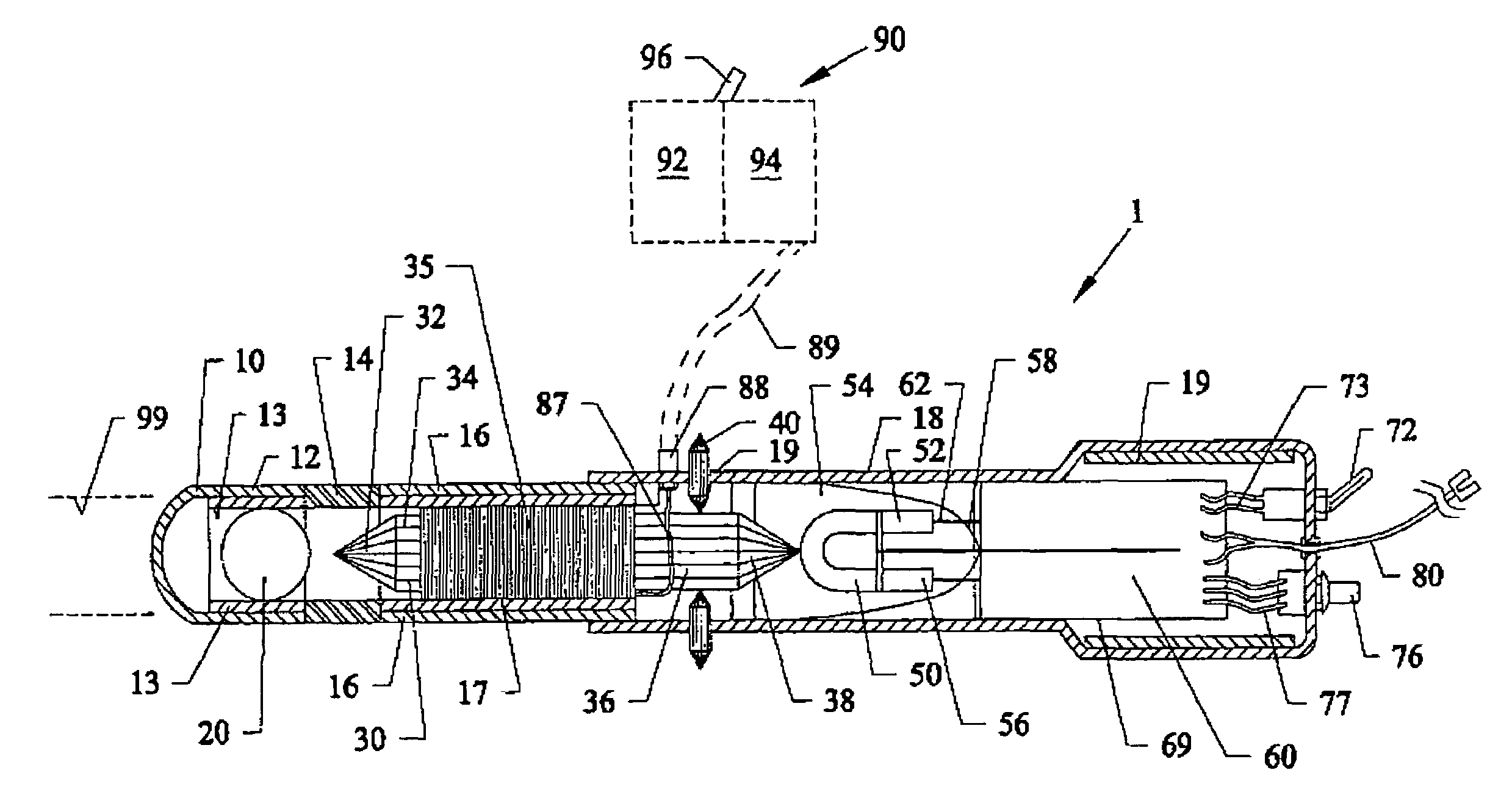
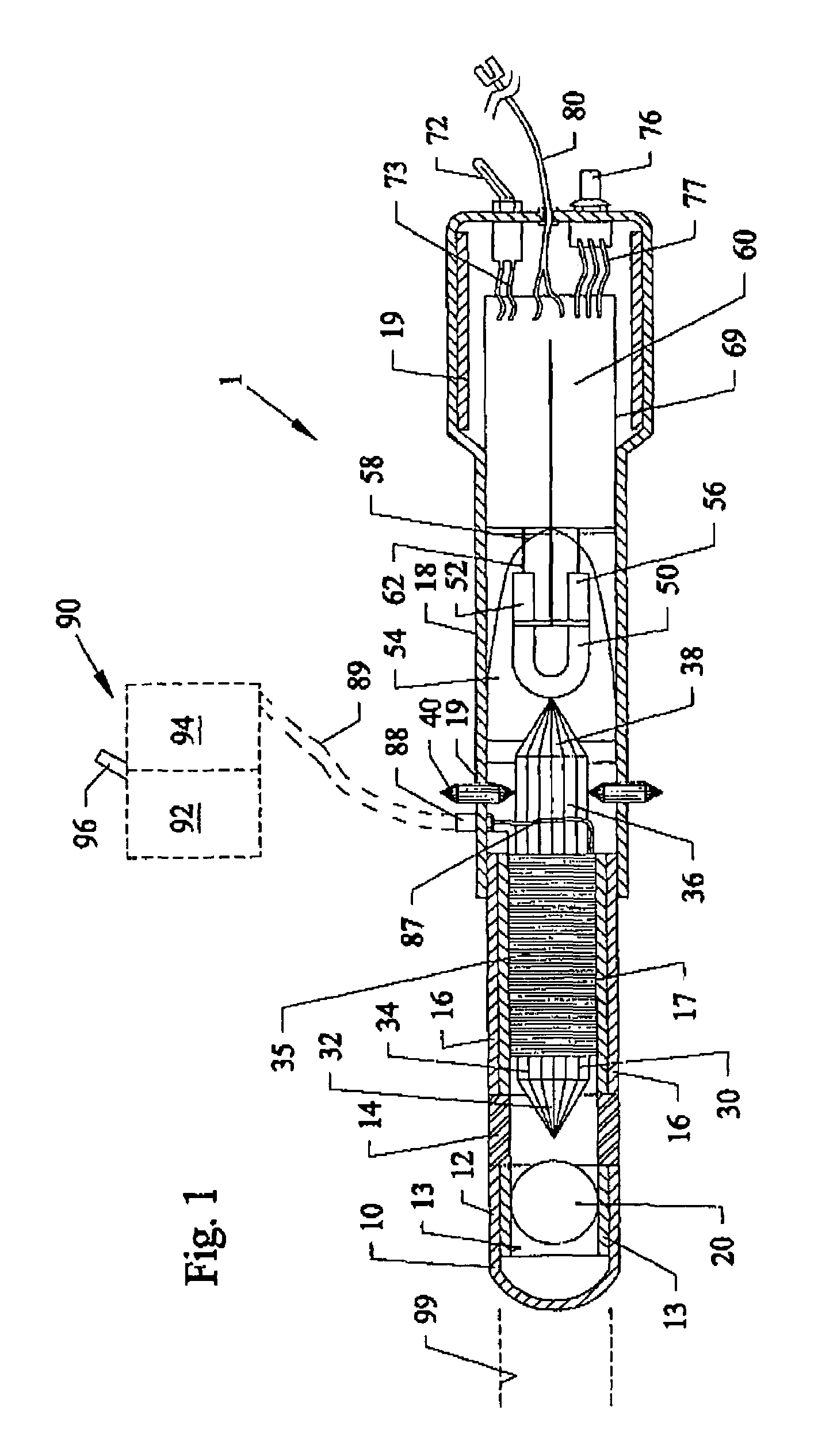
[0025]FIG. 1 is a cross-sectional view of a novel pulse cam device invention 1. The device 1 can include a lens emitting end cap 10 and sleeve 12 which can be formed from a flexible transparent plastic, and the like. Within sleeve 12, can be a secondary cylindrical sleeve also formed from a plastic transparent material that can be used to support a divergent lens 20 as a combined diffuser and amplifier, such as but limited to a crystal sphere formed from silicon dioxide, quartz, and the like. In the preferred embodiment, the sphere used as lens 20 can have a diameter of approximately 4.5 cm.

[0026]The base of the cap and sleeve 12 can...


PUM


Abstract

Battery powered and wall plug powered handheld therapy devices for treating a variety of ailments such as inflammations, nerve problems, joint pain, muscle pain, as well as gall bladder type problems. The device can have a multi-faced shaped emitting main crystal with side crystals that can be used with a flashing strobe light source to generate variable frequency pulses toward the effected body part to be treated. Alternatively, or additionally, the device can use an electromagnetic type generator to generate fixed frequency signals toward an effected body area to be treated. Up to approximately six small crystals or more can be positioned to a base portion of the emitting crystal on each of the six faces of the emitting crystal. The side crystals can be used as antennas to receive ambient energy in order to be focused by the main crystal. Hand grips or a floor based stand can be used to elevate the device up to approximately 18 inches above the patient. Effective treatment with the device has been achieved within approximately 2 minutes of use.

Description

[0001]This invention relates to medical devices, and in particular to methods and apparatus for generating emissions and focusing the energy and emissions through a light pulse powered handheld tool unit or an electromagnetic powered tool or a combination tool for therapeutic treatments.BACKGROUND AND PRIOR ART[0002]Ultrasound and vibratory type emitting devices have been used for medical therapeutic applications over the years. Various types of therapeutic devices have been proposed that apply ultrasonic oscillations and vibrations directly to an affected body part so as to relax muscles, quicken blood flow circulation, enhance healing of the skin, etc. See For example, U.S. Pat. No. 4,708,127 to Abdelghami; U.S. Pat. Nos. 5,230,334 and 6,113,559 to Klopotek; and U.S. Pat. No. 5,989,202 to Noda et al.[0003]However, these devices and systems have practical type limitations. For example, most of these devices are limited to direct contact of a portion of the device itself against the...

Claims


Application Information

Patent Timeline
Patent Type & Authority Patents(United States)
IPC IPC(8): A61B18/18
CPCA61N5/0613A61N2005/0654A61N2005/0644A61N2005/0631
Inventor CROSBY, CHARLESSAYRE, W. PAULDOWNES, DICK
Owner CROSBY ADVANCE MEDICAL SYST
Learn More