
Particle packing of microdevice

a micro-device and particle technology, applied in the field of particle packaging of micro-devices, can solve the problems of difficult automation, difficult to adapt to automation, and require the use of micro-devices having a relatively complex design and/or construction

Active Publication Date: 2006-07-18
AGILENT TECH INC
View PDF12 Cites 18 Cited by
  • Summary
  • Abstract
  • Description
  • Claims
  • Application Information

AI Technical Summary

Benefits of technology

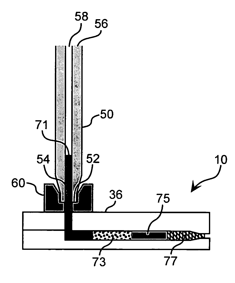
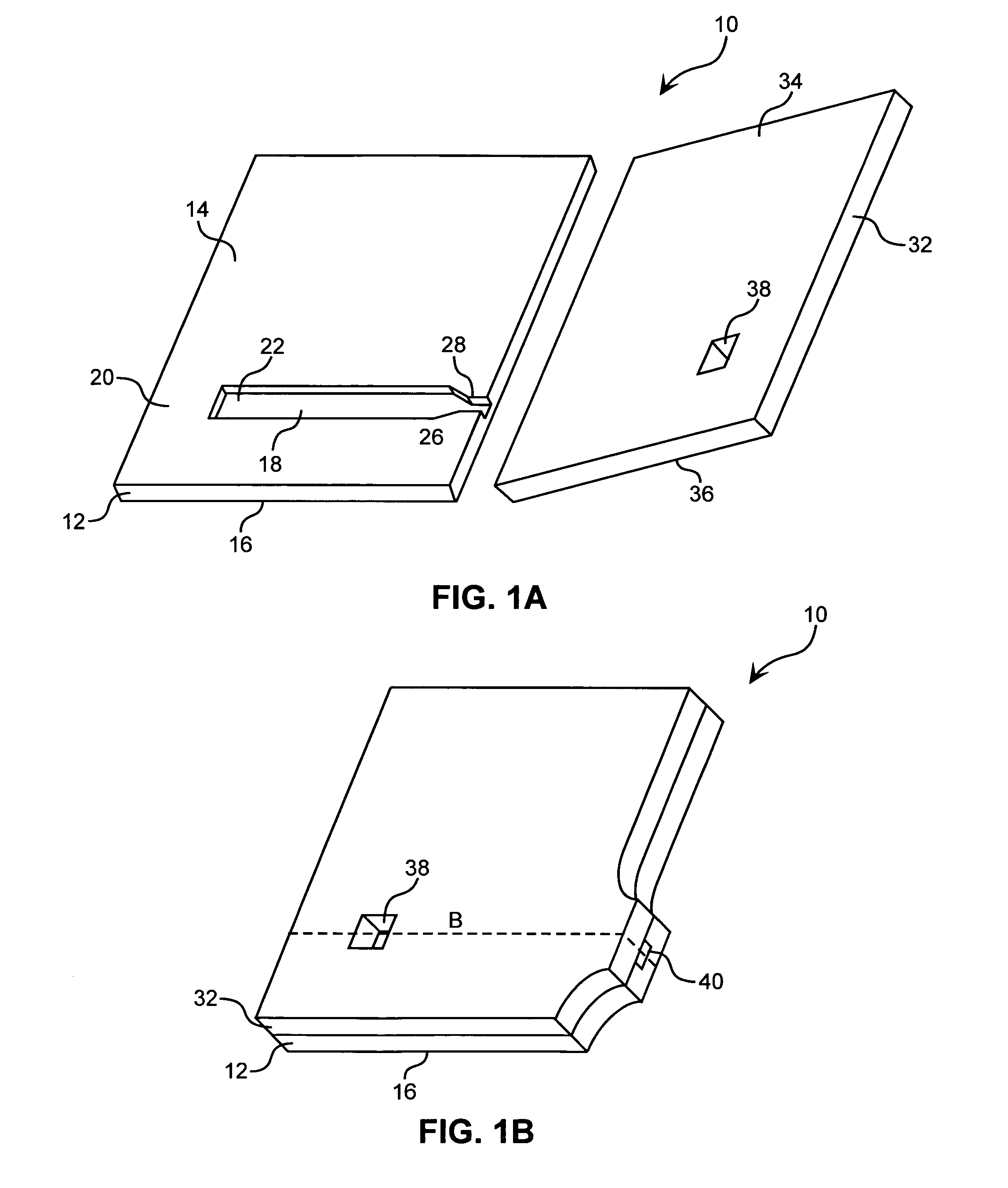
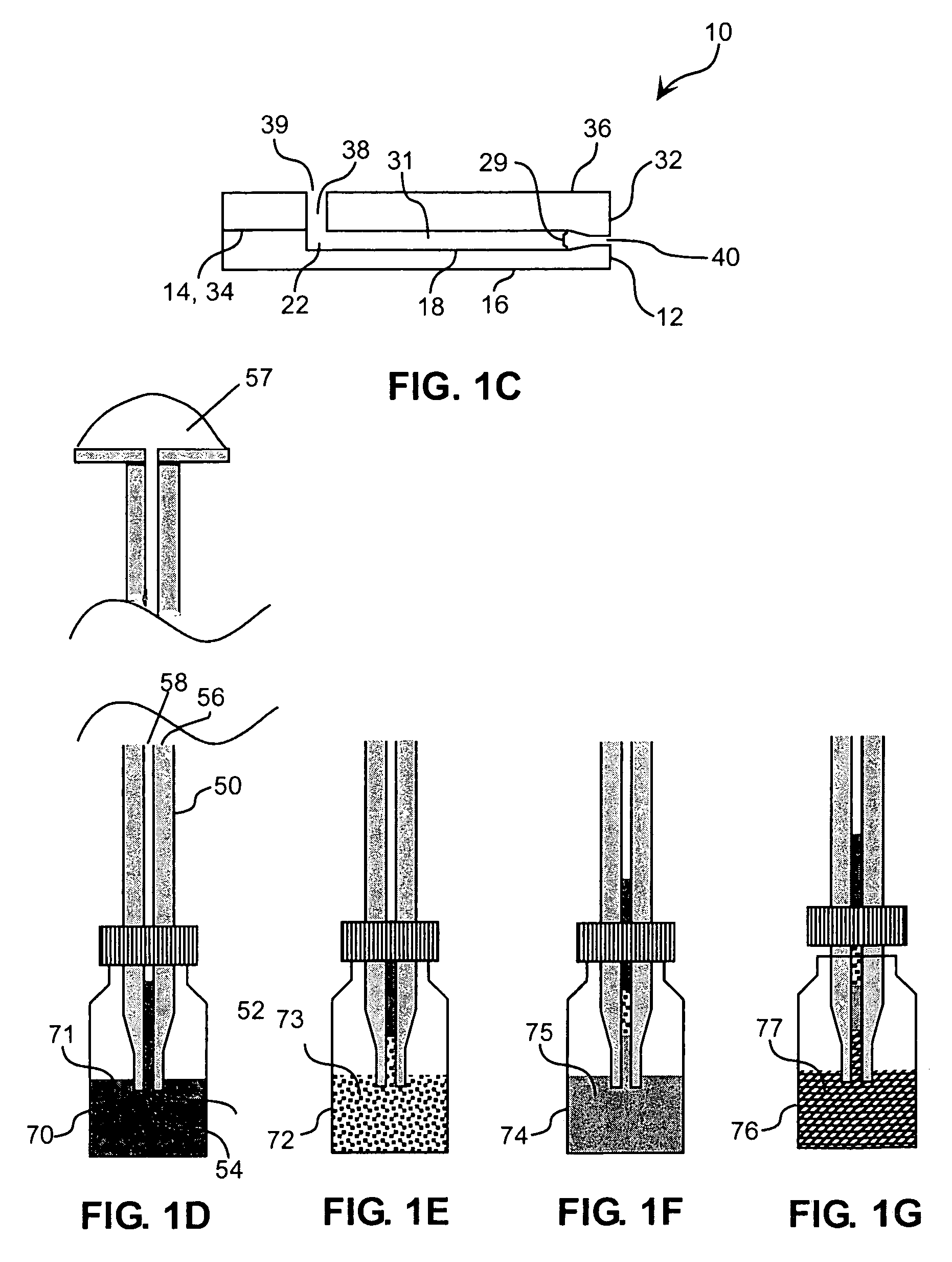
The present invention provides improved methods and apparatuses for controlling the introduction and packing of particles into microdevices. The invention allows for the introduction of particles into microdevices in a more efficient and controlled manner. The apparatus includes a microdevice and a dispenser, which can be easily aligned and filled with particles and fluid or slurry. The invention also allows for the transport of different slurries or combinations of fluids and slurries containing particles of different sizes and functionalities. The particles can form a particle bridge in the bridging zone of the microdevice. Overall, the invention provides a more efficient and controlled way to introduce particles into microdevices for various applications.

Problems solved by technology

In general, these techniques require the use of microdevices having a relatively complex design and / or construction.
Furthermore, these techniques generally do not give reproducible results and are not easily adaptable for automation.
However, this method is difficult to implement for at least two reasons.
Second, weir structures of microfluidic devices require exacting dimensional precision for operability.
Such precision is generally difficult to achieve and maintain for microdevices made from flexible polymeric materials such as polyimide.
Thus, the microdevice loading technology therein suffers from some of the same drawbacks as the technology described above.
Regardless of whether the capillary is permanently attached to the microdevice, the precision needed for such capillary insertion operations are not easily adapted for automation.
Thus, it should be evident that while this approach avoids the complexities associated the manufacture of weirs, such complexities are replaced with the manufacturing challenges associated with specialized microconduit designs and geometries required for the application of centripedal forces.
Thus, there is an unrecognized need in the art for improved apparatuses and methods for introducing particles into microdevices.

Method used


Image

  • Particle packing of microdevice
  • Particle packing of microdevice
  • Particle packing of microdevice

Examples


Embodiment Construction

[0023]Before the invention is described in detail, it is to be understood that unless otherwise indicated this invention is not limited to particular materials, components or manufacturing processes, as such may vary.

[0024]It is also to be understood that the terminology used herein is for purposes of describing particular embodiments only, and is not intended to be limiting. It must be noted that, as used in the specification and the appended claims, the singular forms “a,”“an” and “the” include plural referents unless the context clearly dictates otherwise. Thus, for example, reference to “a dispensing orifice” includes a single dispensing orifice as well as a plurality of dispensing orifices, reference to “a conduit” includes one or more conduits, and the like.

[0025]In this specification and in the claims which follow, reference will be made to a number of terms which shall be defined to have the following meanings:

[0026]The term “conduit” as used herein refers to a three-dimensi...


PUM

PropertyMeasurementUnit
pressureaaaaaaaaaa
pressureaaaaaaaaaa
volume percentaaaaaaaaaa

Abstract

Provided are apparatuses and methods for introducing particles into a microdevice conduit. Also provided are microdevices containing a plurality of particles that occupy at least about 25 volume percent of a microconduit. In some instances, particles may controllably form a particle bridge in a bridging zone within a microdevice.

Description

TECHNICAL FIELD[0001]The present invention generally relates to the introduction of particles into a microdevice conduit. More specifically, the invention relates to the application of pressure to a slurry of particles contained in a dispenser to effect transport of the particles into the conduit via slurry flow through a dispensing orifice of the dispenser and an inlet of the microdevice. Optionally, the microdevice conduit may be shaped to control and / or eliminate formation of particle bridges therein.BACKGROUND[0002]Microfluidics and lab-on-a-chip technologies, also referred to as microdevice technologies, have been proposed for use in the field of analytical and bioanalytical chemistry, particularly in applications that employ fluids that are rare, expensive, and / or available in limited amounts. Such applications include, for example, proteomics, and genomics. The small size of microdevices allows for the analysis of minute quantities of sample. In addition, because microdevices...

Claims


Application Information

Patent Timeline
Patent Type & Authority Patents(United States)
IPC IPC(8): B65B1/04G01N30/56G01N35/00
CPCG01N30/56B01J2219/00466G01N2035/00574G01N2030/565
Inventor YIN, HONGFENGKILLEEN, KEVIN P.BRENNEN, REID A.EFFELSBERG, UWE
Owner AGILENT TECH INC
Learn More