Computer cooling system and method

Active Publication Date: 2006-07-11
HEWLETT-PACKARD ENTERPRISE DEV LP +1
View PDF22 Cites 76 Cited by
  • Summary
  • Abstract
  • Description
  • Claims
  • Application Information

AI Technical Summary

Problems solved by technology

The components of both cards and blades generate large amounts of heat that must be dissipated.

Method used


Image

  • Computer cooling system and method
  • Computer cooling system and method
  • Computer cooling system and method

Examples


Embodiment Construction

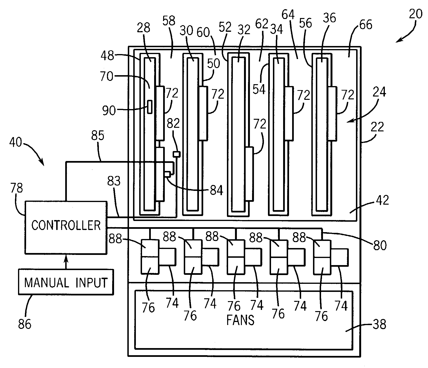
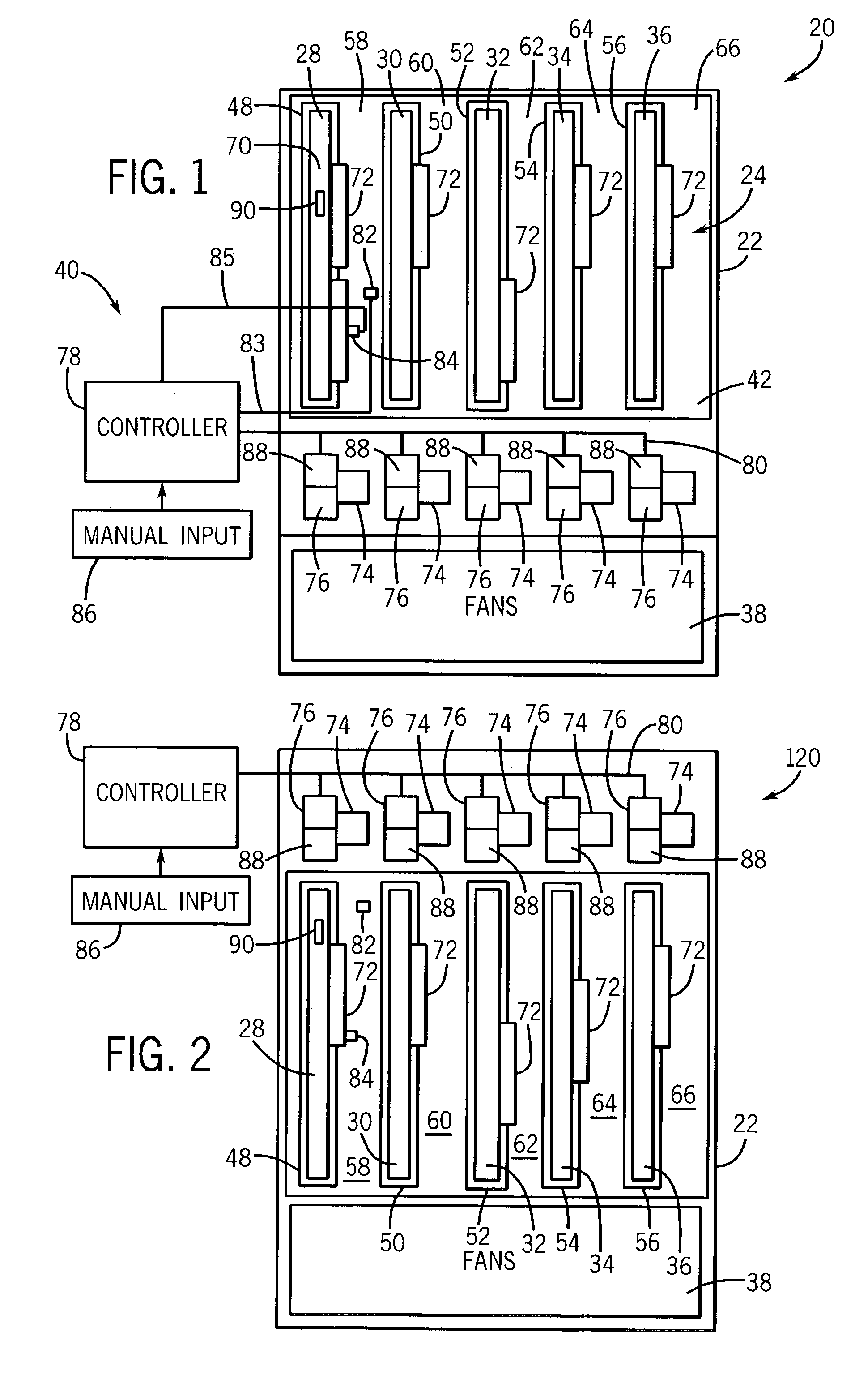
[0021]FIG. 1 is a schematic view of a computer system 20 which generally includes enclosure 22, mother board or backplane 24, replaceable units 28, 30, 32, 34, 36, forced air cooling system 38 and air flow blocking system 40. Enclosure 22 generally comprises one or more structures that support and substantially surround or enclose at least backplane 24, replaceable units 28, 30, 32, 34, 36, cooling system 38 and at least portions of air blocking system 40. In one embodiment, enclosure 22 may comprise a chassis and a lid or cover. The exact configuration of enclosure 22 may vary depending upon the particular characteristics of computer system 20.

[0022]Backplane 24 is supported within enclosure 22 and includes printed circuit board 42 and connectors 48, 50, 52, 54 and 56. Connectors 48, 50, 52, 54 and 56 are generally configured to electronically mate with replaceable units 28, 30, 32, 34 and 36, respectively. In one embodiment, connectors 48, 50, 52, 54 and 56 comprise slot or edge c...


PUM


Abstract

A computer system includes an enclosure, a forced air cooling system configured to create air flow within the enclosure, a printed circuit board and an air flow blockage member. The printed circuit board is within the enclosure and includes a plurality of connectors including a first connector and a second connector separated by a first space. The air flow blockage member is proximate the first space and is movable between at least a first open position and a second open position distinct from the first open position.

Description

CROSS-REFERENCE TO RELATED PATENT APPLICATIONS[0001]The present application is related to co-pending U.S. patent application Ser. No. 10 / 459263 entitled COMPUTER COOLING SYSTEM AND METHOD by Michael A. Brooks and Thane M. Larson and filed on the same date herewith, the full disclosure of which is hereby incorporated by reference.BACKGROUND OF THE INVENTION[0002]Computer systems typically employ a motherboard or backplane to which are connected a plurality of individual cards or blades. Cards typically carry a variety of different components such as central processing chips, IO devices, passive electronics and the like. Blades typically include such components as switches, routers, hard disk drives, modems, complete systems on a card and the like. The components of both cards and blades generate large amounts of heat that must be dissipated. Such systems typically include a forced air cooling system in which fans direct cooling air across the cards or blades.[0003]In one known system...

Claims


Application Information

Patent Timeline
IPC IPC(8): H05K7/20G06F1/20
CPCG06F1/20H05K7/20836H05K7/20718
Inventor LARSON, THANE M.BROOKS, MICHAEL A.
Owner HEWLETT-PACKARD ENTERPRISE DEV LP
Why Eureka
Try Eureka