
Shielded pole writer

Inactive Publication Date: 2006-07-11
MAXTOR
View PDF22 Cites 63 Cited by
  • Summary
  • Abstract
  • Description
  • Claims
  • Application Information

AI Technical Summary

Benefits of technology

[0011]In view of the foregoing, a broad objective of the present invention is to provide a perpendicular recording arrangement with improved write characteristics.
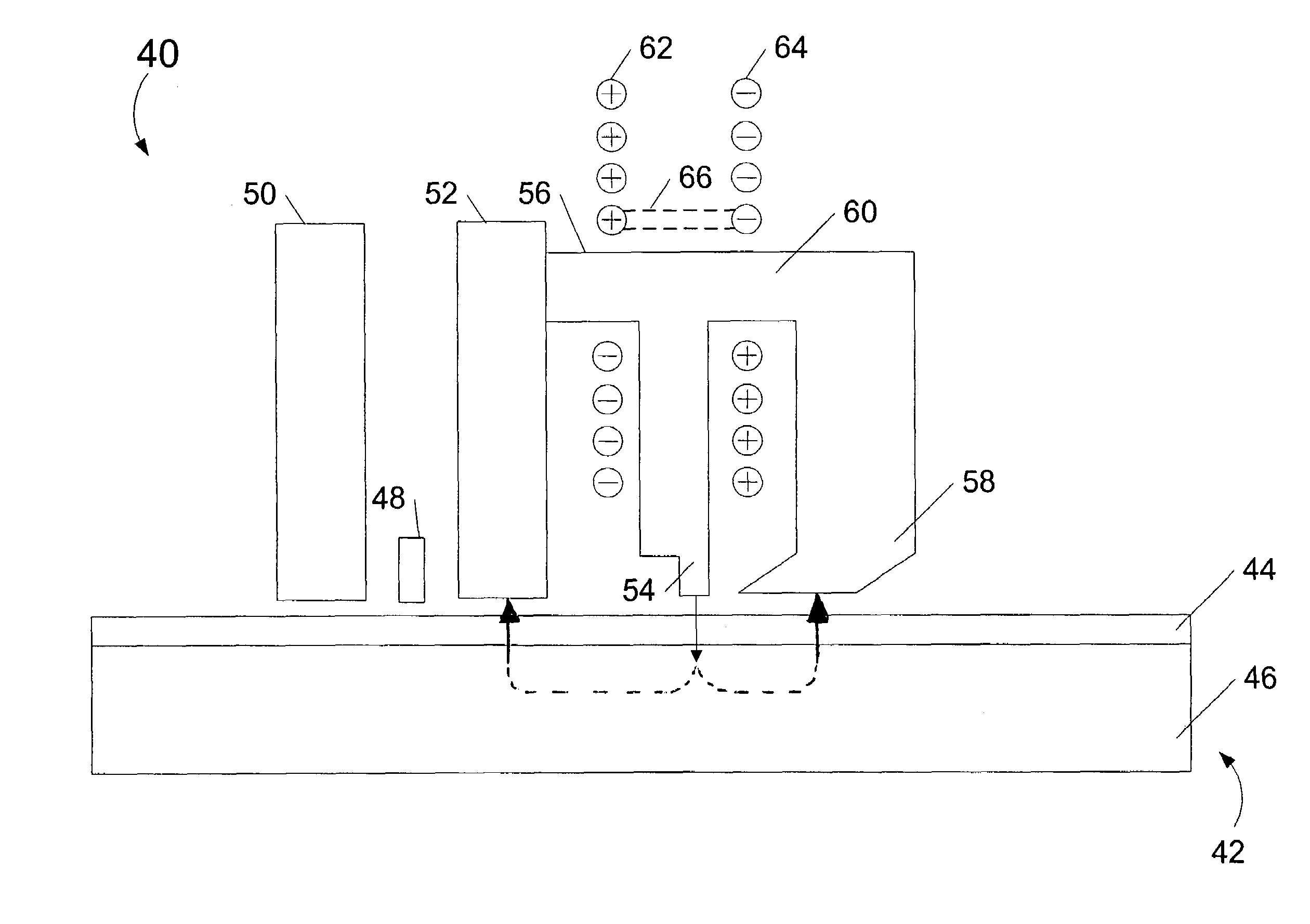
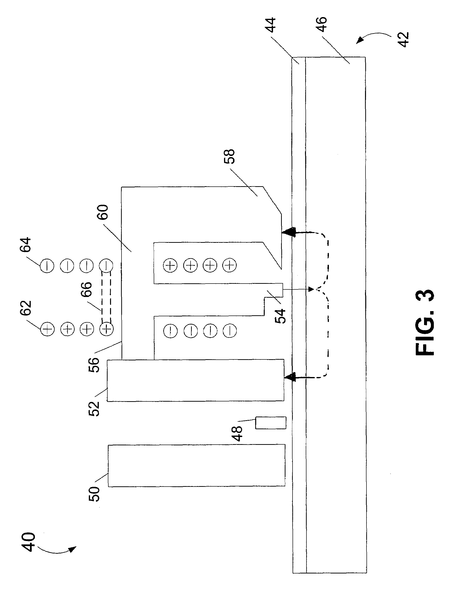
[0014]A first magnetic via may magnetically connect the write pole to the second shield and a second magnetic via may magnetically connect the write shield to the write pole. The cross-sectional area of the first magnetic via may be substantially equal to the cross-sectional area of the second magnetic via. The cross-sectional area of the first magnetic via may be substantially smaller than the cross-sectional area of the second magnetic via. The first magnetic via may be designed to restrict the amount of magnetic flux flowing therethrough as compared to the second magnetic via.

Problems solved by technology

It has been later discovered that the predictions of a low return field in the region of the face of the write shield were not accurate under high current conditions in the electrical coils.
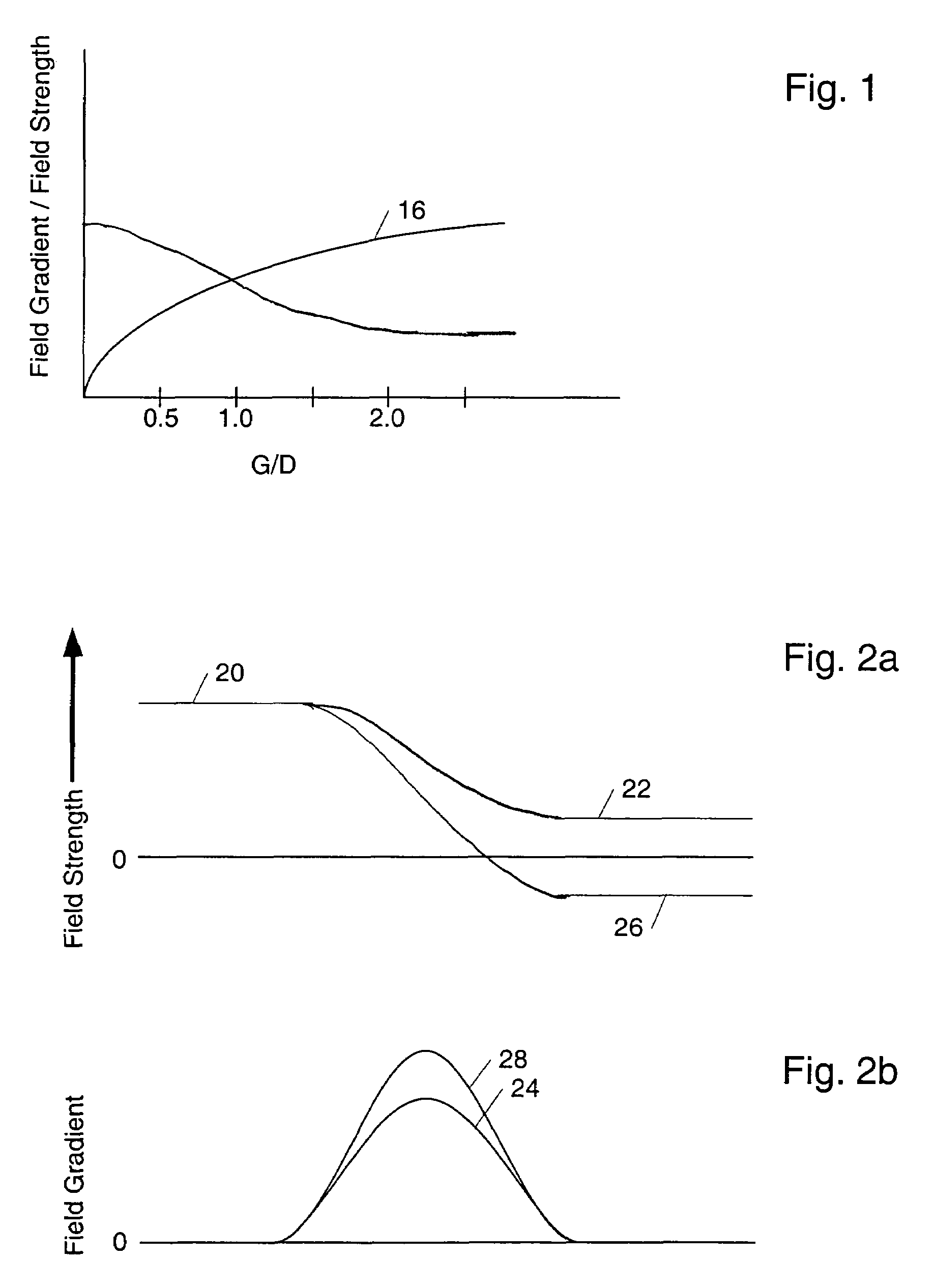
Since the design was unshielded and the write shield had a relatively large surface facing toward the media, the write field gradient was not as high as is desired for high density data recording.

Method used


Image

  • Shielded pole writer
  • Shielded pole writer
  • Shielded pole writer

Examples


Embodiment Construction

[0034]Reference will now be made to the accompanying drawings, which assist in illustrating the various pertinent features of the present invention. Although the present invention will now be described primarily in conjunction with disk drives, it should be expressly understood that the present invention may be applicable to other applications where magnetic recording of data is required / desired. In this regard, the following description of a disk drive is presented for purposes of illustration and description. Furthermore, the description is not intended to limit the invention to the form disclosed herein. Consequently, variations and modifications commensurate with the following teachings, and skill and knowledge of the relevant art, are within the scope of the present invention. The embodiments described herein are further intended to explain best modes known of practicing the invention and to enable others skilled in the art to utilize the invention in such, or other embodiments...


PUM


Abstract

A read / write head for a disk drive having a magnetoresistive (MR) read element and an inductive write element suitable for perpendicular recording of data onto a disk having a media layer in which the data is stored perpendicularly to the planar surface of the disk and a soft underlayer (SUL) underneath the media layer to provide a low reluctance return path for the magnetic recording field. The write element includes a vertically-oriented write pole and a downstream write shield that is magnetically connected to the write pole by a magnetic via. One or more pancake coils are employed to produce a magnetic field that is focused by the tip of the write pole which is relatively smaller than the remainder of the write pole. The design of the write shield, the write pole, the magnetic vias, and the conductive coils is such as to provide an optimal magnetic field gradient and an optimal write field strength.

Description

CROSS-REFERENCE TO RELATED APPLICATIONS[0001]This application claims priority from U.S. Provisional Patent Application No. 60 / 424,431, filed Nov. 7, 2002, entitled “Biased Shielded Pole Writer”, the contents of which are incorporated herein by reference.FIELD OF THE INVENTION[0002]This application relates to techniques and arrangements for write heads in data storage applications, particularly the shielding of write heads for perpendicular recording.BACKGROUND OF THE INVENTION[0003]In hard disk drives, data is written to and read from magnetic recording media, herein called disks. Typically, one or more disks having a thin film of magnetic material coated thereon are rotatably mounted on a spindle. A read / write head mounted on an actuator arm is positioned in close proximity to the disk surface to write data to and read data from the disk surface.[0004]During operation of the disk drive, the actuator arm moves the read / write head to the desired radial position on the surface of the ...

Claims


Application Information

Patent Timeline
IPC IPC(8): G11B5/127
CPCG11B5/1278G11B5/3116G11B5/3967G11B5/315G11B2005/0029
Inventor MALLARY, MICHAELBENAKLI, MOURAD
Owner MAXTOR
Learn More