
Stirring hot plate

a hot plate and stirrer technology, applied in the field of stirring hot plates, can solve the problems of magnetic stir bars clinging around in the beaker, affecting the efficiency of stirring, and the set point of stirring speed may be lost and have to be reset,

Active Publication Date: 2006-07-11
THERMO FISHER SCI ASHEVILLE
View PDF34 Cites 18 Cited by
  • Summary
  • Abstract
  • Description
  • Claims
  • Application Information

AI Technical Summary

Benefits of technology

Enables quick and efficient stirring process transitions with maintained speed settings and ensures user safety by providing effective visual warnings of a hot surface, reducing the risk of accidents and user intervention.

Problems solved by technology

However, with some magnetic stirrers, the stirring speed set point may be lost and have to be reset.
That abrupt decoupling results in the magnetic stir bar clanging around in the beaker.
However, after an operating cycle, when the power is turned off and the fluid container removed, users are less likely to be conscious of the platform being hot-to-the-touch and may not see the illuminated hot-to-the-touch indicator.

Method used


Image

  • Stirring hot plate
  • Stirring hot plate
  • Stirring hot plate

Examples


Embodiment Construction

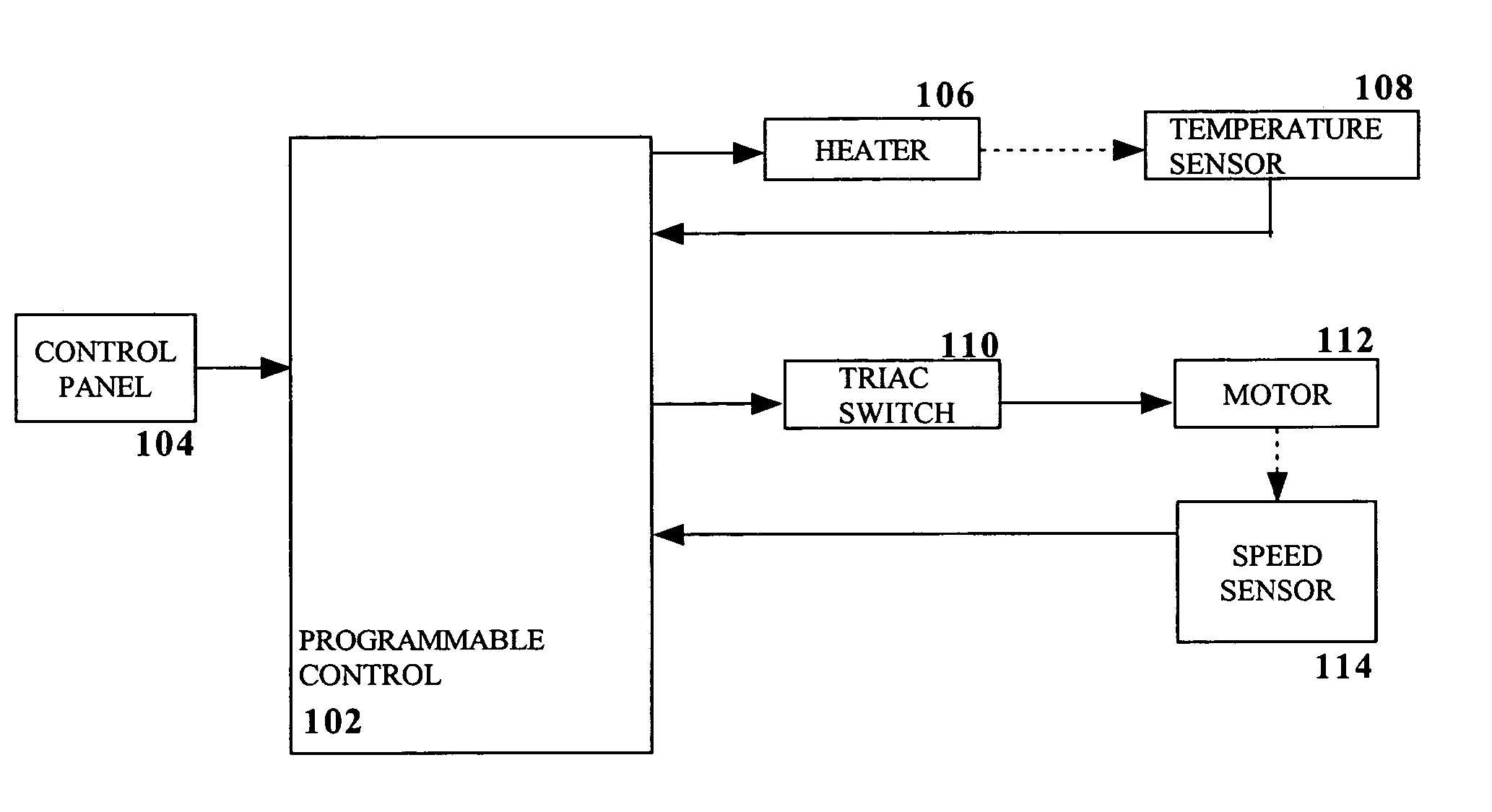
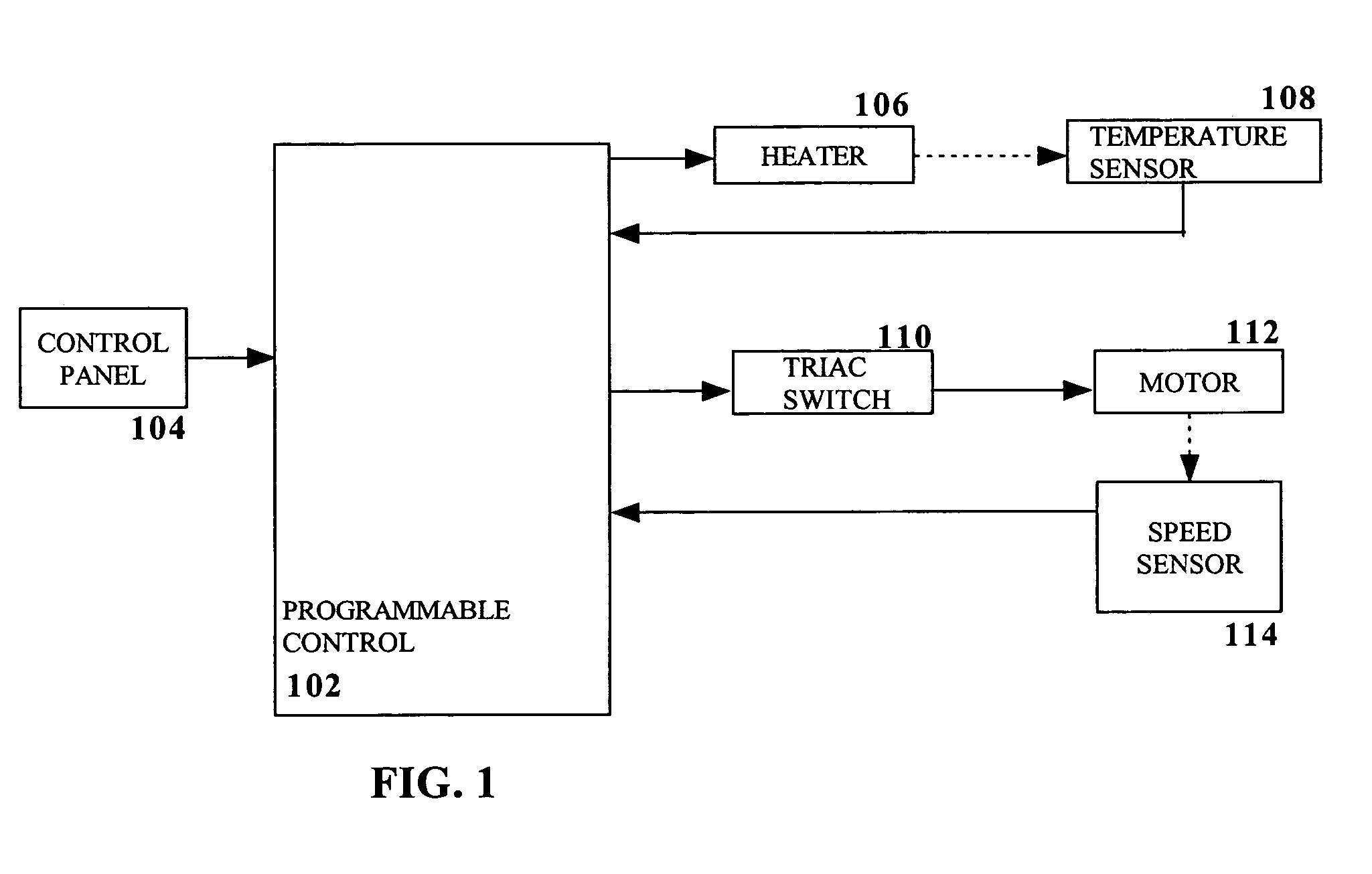
[0017]FIG. 1 illustrates, in block diagram form, the major components of an exemplary stirring hot plate.

[0018]A control panel 104 provides the interface to a user operating the hot plate. An exemplary control panel is shown in FIG. 4 and includes input devices, such as control knobs 402, 404, that permit a user to adjust the heat and stirrer settings of the hot plate. By using these knobs, a desired temperature and RPM setting can be input to the controller 102.

[0019]The control panel 104 also includes output devices, such as LEDs 406, 410, 412 and 7-segment displays 408, that provide to a user indication of how the hot plate is operating. For example, the control panel 104 can display the current temperature of the hot plate or the temperature set point, the stirrer setting, or whether the hot plate is on or off. One particularly useful display is an indicator of whether the hot plate's surface remains hot even though the hot plate has been turned off. One of ordinary skill will r...


PUM


Abstract

A stirring hot plate for simultaneously heating and stirring a mixture includes a phase controlled motor that spins magnets which couple to, and thereby spin, a stir bar within the mixture. In addition to spinning the magnets, the motor includes an operational mode in which the motor is rapidly braked thereby quickly spinning down the stir bar. The stirring hot plate also includes a visual indicator to the user that the platform is hot-to-the-touch that is especially effective when the stirring hot plate is not in use.

Description

RELATED APPLICATIONS[0001]The present application claims the benefit of U.S. Provisional Patent Application Ser. No. 60 / 496,744 entitled STIRRING HOT PLATE, filed on Aug. 21, 2003 and Ser. No. 60 / 547,377 entitled STIRRING HOT PLATE, filed Feb. 24, 2004, the disclosures of which are herein incorporated by reference in their entirety.FIELD OF THE INVENTION[0002]This invention relates generally to laboratory equipment and more particularly, to stirring hot plates.BACKGROUND OF THE INVENTION[0003]Stirring hot plates are widely used in the chemical, medical, food and agricultural technology industries. A stirring hot plate has a stationary base on which the fluid container rests. A magnetic stir bar is inserted into the container, and the magnetic stir bar is coupled by a magnetic field to magnets located beneath the table. Rotating the magnets beneath the table rotates their coupling magnetic fields and causes a corresponding rotation of the magnetic stir bar in the liquid. Simultaneous...

Claims


Application Information

Patent Timeline
Patent Type & Authority Patents(United States)
IPC IPC(8): H05B1/02B01F13/08B01F15/00B01F15/06H05B3/68
CPCB01F13/0006B01F13/0818B01F15/00168B01F15/00175B01F15/00363H05B3/68B01F15/00396B01L7/00H05B1/0247B01F15/00389B01L2300/027B01L2300/1827B01F33/053B01F33/452B01F35/2114B01F35/2115B01F35/2214B01F35/221422B01F35/2215
Inventor MCFADDEN, CURTHERMSEN, KENNETH DAVIDEARLE, ROGER W.EDWARDS, JAMESLEPPERT, KERRY W.JACKSON, ERICGARZ, ERICLOCKWOOD, MARKMEEK, JOHN L.
Owner THERMO FISHER SCI ASHEVILLE
Learn More