
Apparatus and methods for imaging wells drilled with oil-based muds

a technology of resistivity measurement and equipment, which is applied in the field of resistivity logging tools, can solve the problems of limited well coverage, inability to provide full borehole images, and inability to drill economically,

Active Publication Date: 2006-07-11
SCHLUMBERGER TECH CORP
View PDF11 Cites 36 Cited by
  • Summary
  • Abstract
  • Description
  • Claims
  • Application Information

AI Technical Summary

Benefits of technology

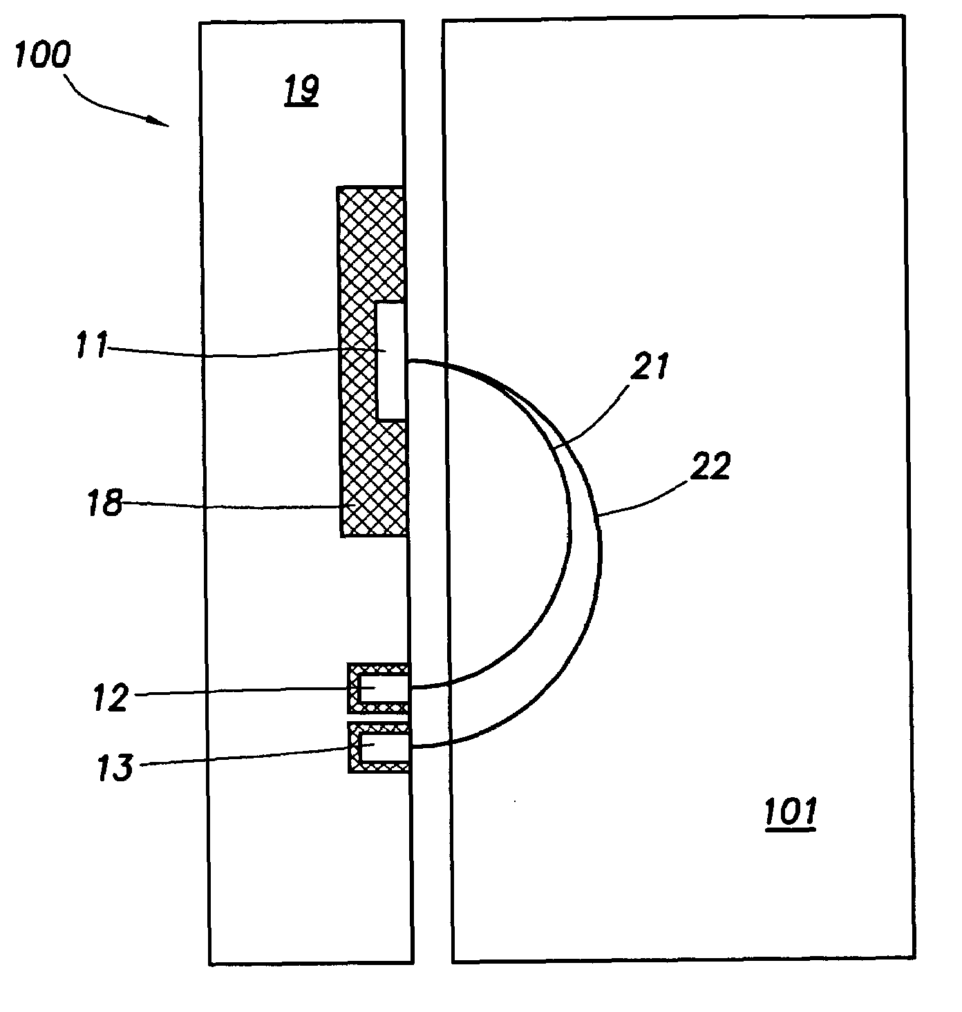
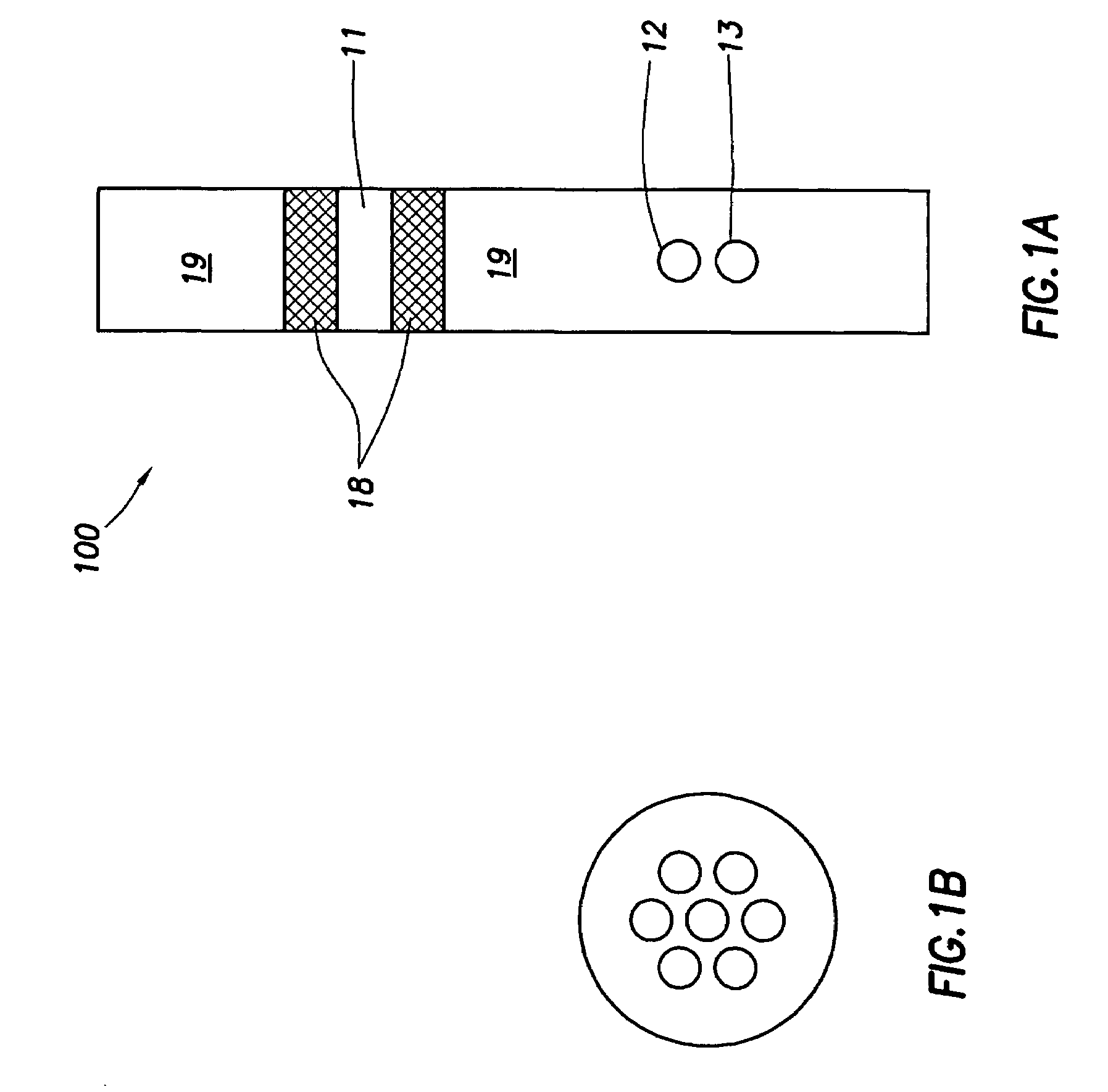
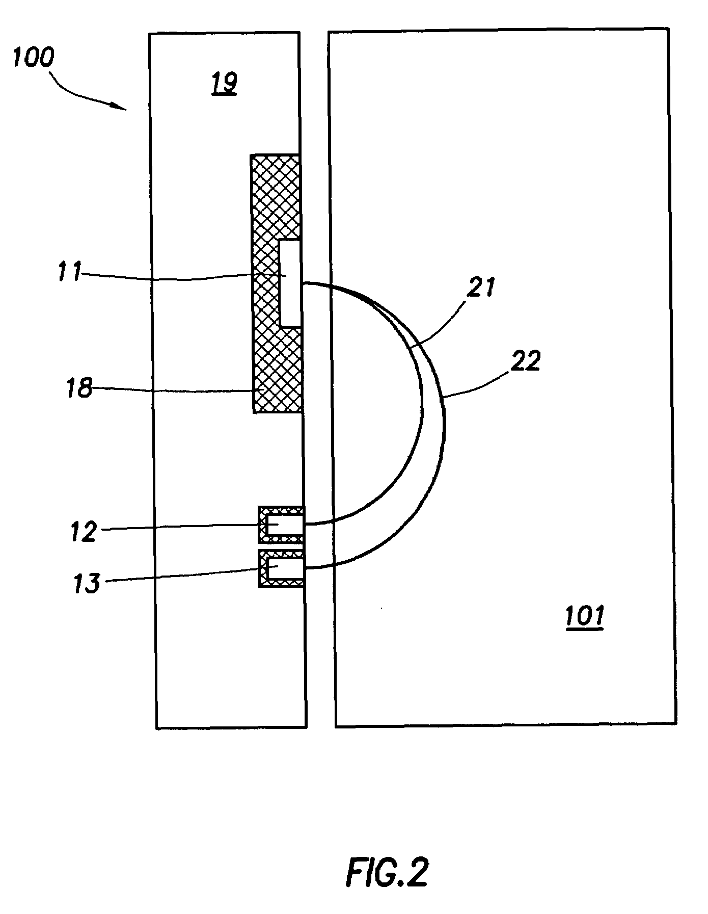
The invention relates to a sensor and method for logging the resistivity of a formation while drilling a well using oil-based mud. The sensor has three electrodes: a current injector electrode, two current return electrodes, and an electrical source. The current injector electrode injects a current into the formation, while the current return electrodes measure the current returning to them. The method involves injecting a current into the formation, measuring the current returning to the electrodes, and repeating this process with another current. The difference between the measurements is used to determine the formation property. The invention allows for more accurate and efficient well drilling.

Problems solved by technology

Many of these reservoirs comprise a series of small targets that on their own would not be economical to drill.
Unfortunately, these tools, GST™, RAB™, and GVR™, are limited to wells drilled with water-based mud (WBM), while most high-angle and horizontal wells are drilled with oil-based mud (OBM).
Thus, this tool can image four sectors of the borehole; however, it does not have enough coverage of the borehole to provide full borehole images.
As such, this tool has the capability to measure formation dip in OBM, but it has no imaging capability.
While progress has been made in the development of wireline OBM tools, the development of logging-while-drilling (LWD) or measurement-while-drilling (MWD) OBM resistivity tools has been relatively slower.
However, ADN™ can only provide a 16-sector density image.
Furthermore, a logging sensor used on an LWD tool may not be able to maintain contact with the borehole wall at all times. Tool standoffs may reduce the accuracy of the measurements.

Method used


Image

  • Apparatus and methods for imaging wells drilled with oil-based muds
  • Apparatus and methods for imaging wells drilled with oil-based muds
  • Apparatus and methods for imaging wells drilled with oil-based muds

Examples


Embodiment Construction

[0034]Embodiments of the invention relate to apparatus and methods for resistivity measurements and formation imaging. A tool in accordance with embodiments of the invention is capable of operating in oil-based muds (OBM) and may be used while drilling. In addition, embodiments of the invention can monitor and / or minimize the tool standoff effects.

[0035]A resistivity logging tool can be based on one of the two sensor mechanisms: electrical dipoles (using generally metallic electrodes) and magnetic dipoles (using generally induction coils or resonant cavities at VHF). Embodiments of the invention relate to tools using metallic electrode sensors.

[0036]Due to high resistivities of typical OBM (Rm>1000 ohm-meters), it is necessary to use current sources capable of high-operating frequencies. With high frequencies, it becomes possible to drive sufficient currents by capacitive coupling through the insulating muds and into rock formations, and to collect currents returning to the electrod...


PUM


Abstract

A resistivity logging sensor for logging while drilling a well using an oil-based mud includes a sensor body; a first current injector electrode disposed on the sensor body, wherein the first current injector electrode is electrically insulated from the sensor body; at least two current return electrodes disposed on the sensor body at a selected distance from the first current injector electrode, wherein the at least two current return electrodes are disposed proximate to each other and are electrically insulated from the sensor body; and an electrical source configured to energize the first current injector electrode with a current having a voltage of no less than 50 mvolts and a frequency of no less than 1 KHz.

Description

CROSS-REFERENCE TO RELATED APPLICATIONS[0001]Not applicable.STATEMENT REGARDING FEDERALLY SPONSORED RESEARCH OR DEVELOPMENT[0002]Not applicable.BACKGROUND OF THE INVENTION[0003]1. Field of the Invention[0004]The invention relates generally to resistivity logging tools. More particularly, the invention relates to tools and methods of resistivity measurements in wells drilled with oil-based muds.[0005]2. Background Art[0006]In order to minimize the effect of water coning, the number of high angle (deviated) and horizontal wells drilled in small and complex reservoirs has increased significantly over the past years. Many of these reservoirs comprise a series of small targets that on their own would not be economical to drill. To make drilling such reservoirs economical, the industry has developed directed drilling techniques to drill deviated or horizontal wells.[0007]Many tools for drilling deviated or horizontal wells are available. Examples include the geosteering tool sold under th...

Claims


Application Information

Patent Timeline
Patent Type & Authority Patents(United States)
IPC IPC(8): E21B47/026G01V3/24
CPCG01V3/24
Inventor TABANOU, JACQUES R.OMERAGIC, DZEVATSEYDOUX, JEANPISONI, ATTILIO C.
Owner SCHLUMBERGER TECH CORP
Learn More