
Optically encoded glass-coated microwire

a micro-wire and optical encoder technology, applied in the direction of insulated conductors, cables, instruments, etc., can solve the problems of reducing the identifying characteristics, and the increase of the size, weight and cost of the marker

Inactive Publication Date: 2006-07-04
DEMODULATION
View PDF12 Cites 6 Cited by
  • Summary
  • Abstract
  • Description
  • Claims
  • Application Information

AI Technical Summary

Benefits of technology

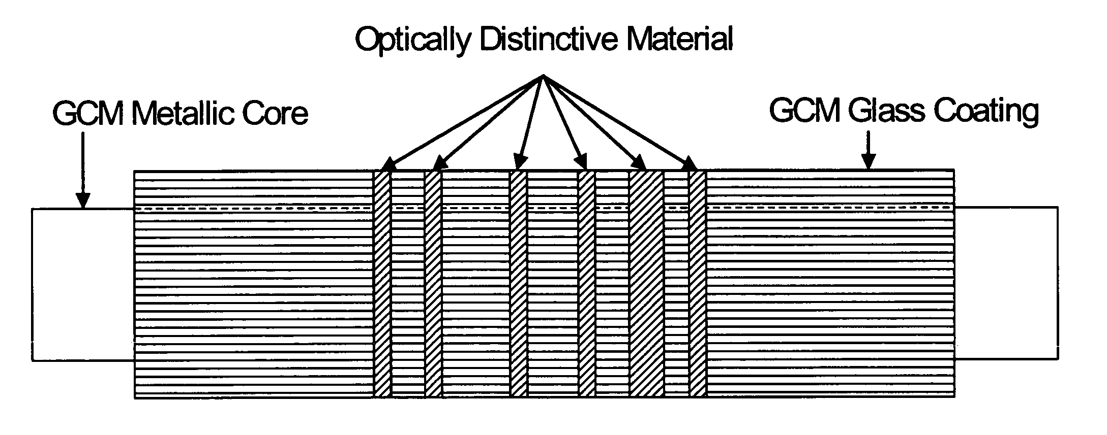
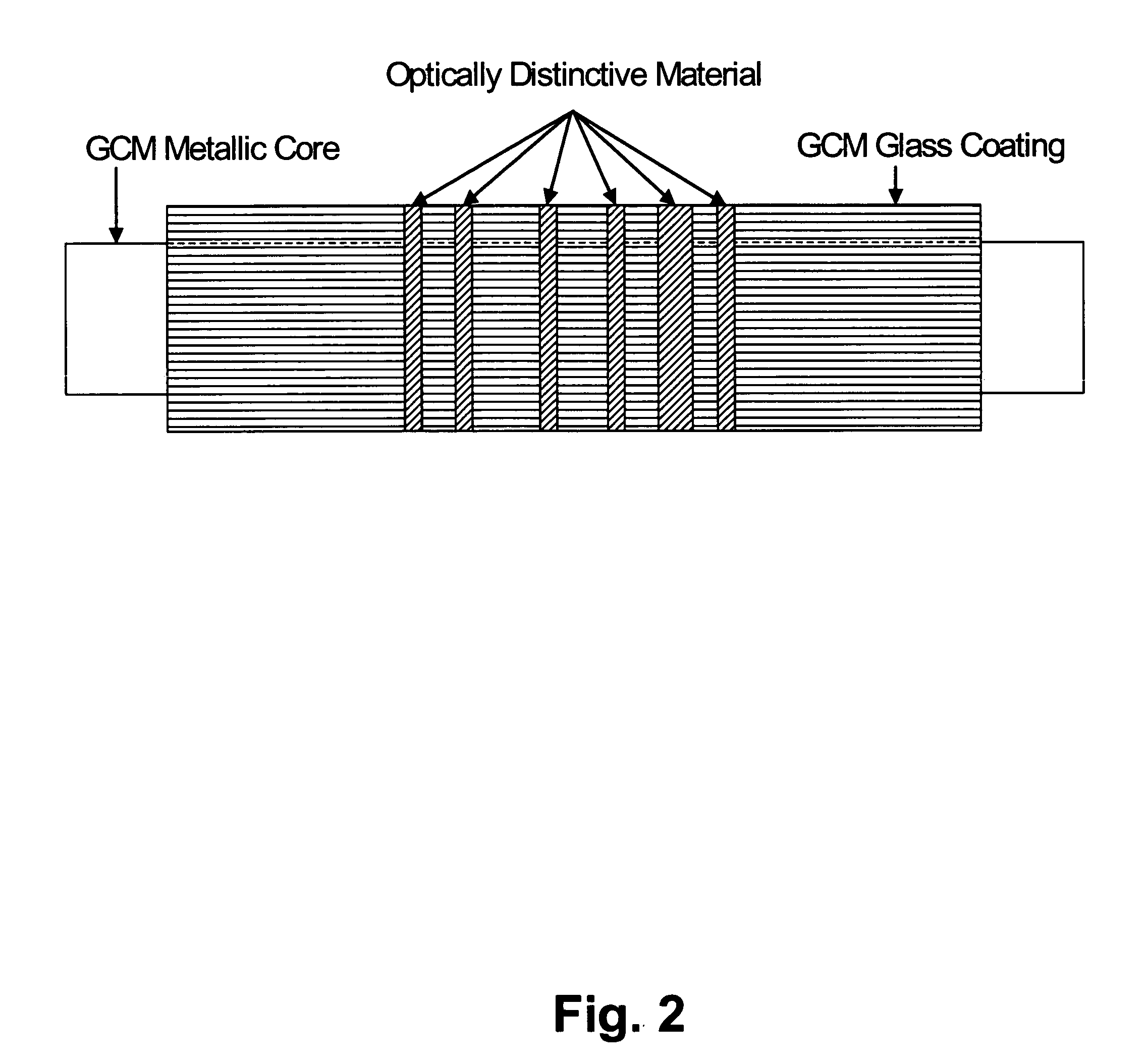
[0011]The present invention provides a multi-bit encoded glass coated microwire and articles produced therefrom. Also provided by the invention is a process for encoding of the amorphous or nanocrystalline alloy GCM and article. Advantageously, the invention obviates the need for multiple segments of GCM when manufacturing an encoded article such as an EAS marker. Surprisingly, it has been discovered that altering either the ferromagnetic amorphous alloy core or the glass outer layer of a GCM enables production of the GCM, as well as articles having multi-bit encoding capability. This is the case even when the encoded marker comprises a single segment of GCM. Encoding is afforded either magnetically, or optically; or by a combination thereof. This feature provides the additional advantage of enabling either redundant or complementary systems to be operative in even a single segment of GCM. A further advantage provided by the instant invention is that encoding of the GCM and articles containing GCM can be encoded either during their production process, at various stages of downstream conversion, or even in the field by the end user.
[0012]Advantageously, glass-coated amorphous or nanocrystalline alloy GCM marker produced in accordance with the invention is lightweight, small, inexpensive to construct and highly reliable in operation. Optical encoding of the GCM is readily accomplished by numerous means. When encoded both magnetically and optically, the glass coated microwire of the invention provides redundant authentication or complimentary functions, such as anti-theft capability in conjunction with multi-bit authentication.

Problems solved by technology

They increase the size, weight and cost of the marker and, unless accurately positioned thereon, decrease its identifying characteristics.

Method used


Image

  • Optically encoded glass-coated microwire
  • Optically encoded glass-coated microwire
  • Optically encoded glass-coated microwire

Examples


example 1

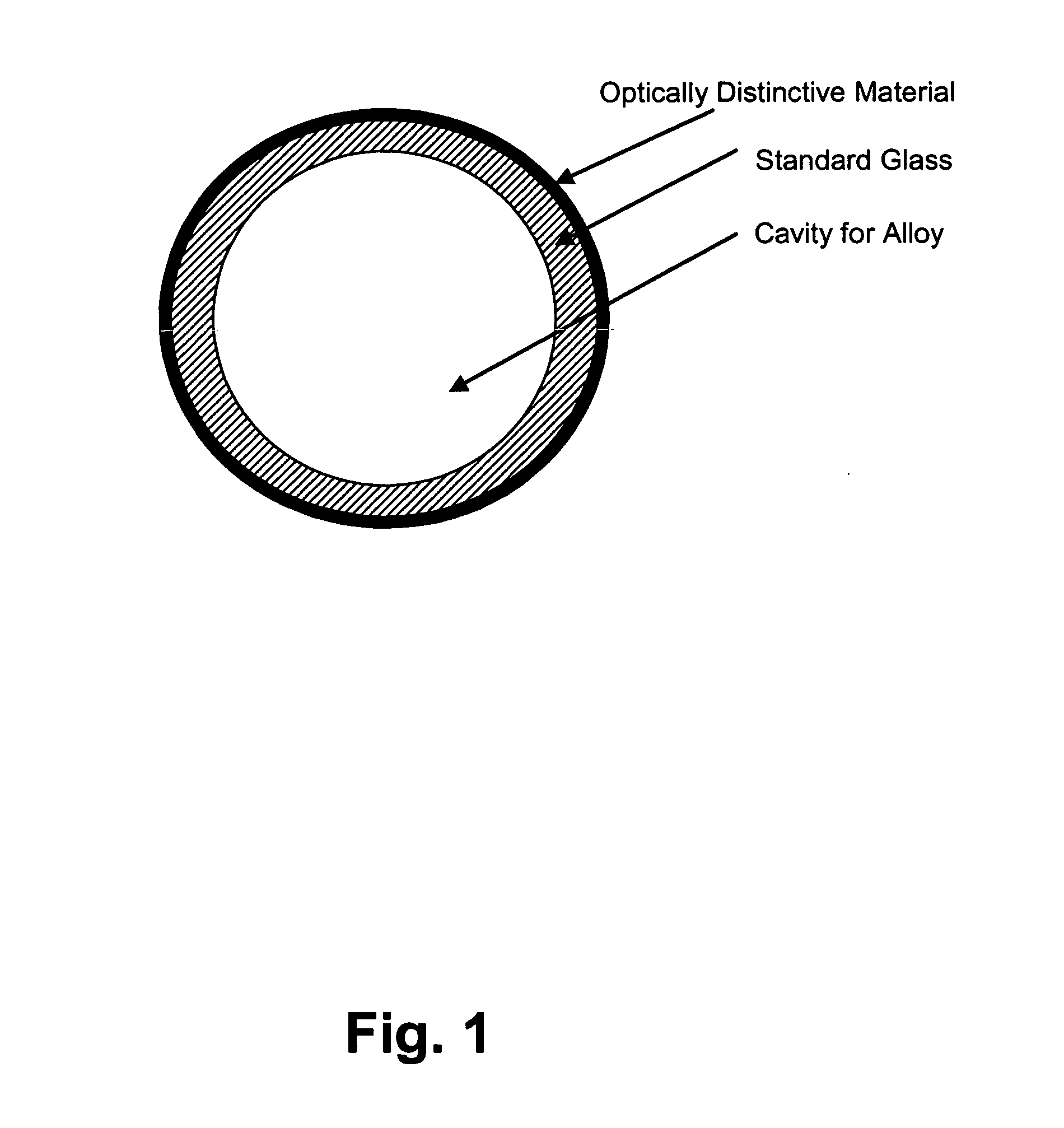
[0057]An ingot composed of an amorphous-forming metallic alloy is prepared by loading the appropriate weights of constituent elements into a quartz tube that is sealed at one end. The other end of this quartz tube is connected to a pressure-vacuum system to allow evacuation and back-filling with Ar gas several times to ensure a low oxygen Ar atmosphere within the quartz tube. Next, the closed end of the quartz tube in which the elements reside is introduced into a high frequency induction-heating coil. With the application of radio frequency (“r.f.”) power, the elements inside the tube are caused to heat and melt into a stirred, homogeneous metallic alloy body. When the r.f. power is shut off, the alloy body is allowed to cool to room temperature in the Ar atmosphere. Once cooled, the same metallic alloy body is inserted into the bottom of a vertically disposed glass tube 1 (preform), having 6-mm diameter that is sealed at the lower end, as depicted in FIG. 5. The upper end of this ...

example 2

[0059]GCM for use in optical-based authentication is produced using the methods, materials and apparatuses of Example 1, except that the borosilicate composition used to form the glass coating of the GCM now contains a small amount of the rare earth element Europium (Eu). The incorporation of Eu into the glass composition results in the optical behavior shown in FIG. 6, wherein the detectable emission of light at 611 nm occurs when the glass is illuminated by broadband light having wavelengths between 420–600 nm. Note the dramatically increased output signal from the glass of this example, when compared to that of Example 1. Furthermore, the sensitive effect of Eu concentration on the resultant emission strength is shown thereby, providing a complementary means for providing authentication.

example 3

[0060]GCM for use in optical-based authentication is produced using the methods, materials and apparatuses of Example 1, except that the borosilicate composition used to form the glass coating on the GCM now contains a small portion of any one of the rare earth elements: Cerium (Ce), Praseodymium (Pr), Neodymium (Nd), Samarium (Sm), Europium (Eu), Gadolinium (Gd), Terbium (Tb), Dysprosium (Dy), Holmium (Ho), Erbium (Er), Thulium (Tm), Ytterbium (Yb), and Lutetium (Lu). Each individual rare earth element lends its own unique contribution to the host glass' intrinsic optical signature, which can then be exploited for authentication purposes. As for the Eu in Example 2, the unique optical signature due to the rare earth component is a function of the concentration. FIG. 7 shows optical emission spectra of an alkali borosilicate base glass of the same base glass doped with 1 mole % of Terbium in the form Tb4O7. Note how output increases rapidly with the addition of Tb4O7.


PUM

PropertyMeasurementUnit
grain sizeaaaaaaaaaa

Abstract

A drawn glass-coated metallic member has a thermal contraction coefficient differential such that the thermal contraction coefficient of the glass is less than that of the metallic member. The thermal contraction coefficient differential is maintained within a predetermined range during drawing. Drawn glass is placed under residual compression, interfacial bonding between said glass and said wire is substantially uniform, and surface cracking and bond breaks between metal and glass are substantially prevented. Optical properties of the glass coated microwire provide a basis for enabling multi-bit encoding capability. Advantageously data encoding is achieved optically, magneto-optically or using a combined magnetic and optical encoding mechanism. The duplex material constitution of the glass coated microwire permits imparting of data thereon by selection and processing of the glass. Data implantation is readily achieved in-line, during an initial drawing operation, or as a separate post-draw process. Reading of data on optically encoded glass coated microwire is readily accomplished by optical or magnetic methodology, or a combination thereof.

Description

BACKGROUND OF THE INVENTION[0001]1. Field of the Invention[0002]This invention relates to glass-coated wire; and more particularly, to a glass coated microwire (GCM) that is optically encoded to provide an article having multi-bit data read / write capability.[0003]2. Description of the Prior Art[0004]Electronic Article Surveillance (EAS) systems are used to electronically detect goods that have not been authorized when they are removed from a retailer. The systems comprise a marker attached to the goods and a sensor mechanism. The retailer can neutralize the marker when he wishes to authorize the removal of the goods, for example when the items have been legitimately purchased.[0005]One type of EAS marker, termed harmonic or electromagnetic, is disclosed by U.S. Pat. Nos. 4,484,184 and 5,921,583. Such a marker comprises a plurality of strips or wire segments of ferromagnetic amorphous magnetic material that resonate electromagnetically and thereby generate harmonics in the presence o...

Claims


Application Information

Patent Timeline
Patent Type & Authority Patents(United States)
IPC IPC(8): H01B7/00
CPCG06K19/06018G06K19/06187Y10T29/49194Y10T29/49117
Inventor CLARE, ALEXIS G.KING, WESLEY A.LACOURSE, WILLIAM C.LIEBERMANN, HOWARD H.O'KEEFE, JR., JAMES E.
Owner DEMODULATION
Learn More