
Drive circuit having improved energy efficiency for implantable beneficial agent infusion or delivery device

a technology of driving circuit and beneficial agent, which is applied in the direction of device details, instruments, device details, etc., can solve the problems of more drug than intended to reach the patien

Inactive Publication Date: 2006-07-04
MEDTRONIC INC
View PDF29 Cites 199 Cited by
  • Summary
  • Abstract
  • Description
  • Claims
  • Application Information

AI Technical Summary

Benefits of technology

[0009]The present invention is an implantable beneficial agent or drug infusion or delivery device which features a unique energy conservation circuit and method. In one embodiment of the present invention, the safety valve assembly comprises a piezo-electric membrane and a corresponding seal mechanically openable in response to actuation of the membrane, where the seal is placed into an open position only upon the membrane being actuated, deflected or moved t...

Problems solved by technology

Thus, one drawback to active devices which feature pumps that are not normally closed, such as those disclosed in U.S. Pat. Nos. 5,277,556; 5,224,843 and 5,219,278 is that in the vent the device malfunctions or changes occur in the fluid pathway, then more drug than intended may reach the patient.
Similar risks are inherent in passive devices which, should the flow regulator fail or the pressure reservoir be over pressurized, may lead to more drug than intended to reach the patient.

Method used


Image

  • Drive circuit having improved energy efficiency for implantable beneficial agent infusion or delivery device
  • Drive circuit having improved energy efficiency for implantable beneficial agent infusion or delivery device
  • Drive circuit having improved energy efficiency for implantable beneficial agent infusion or delivery device

Examples


Embodiment Construction

[0019]This patent application hereby incorporates by reference into the specification hereof each of the following patent applications, each in its respective entirety: (1) U.S. patent application Ser. No. 09 / 239,306 to Haller et al. entitled “System for Locating Implantable Medical Device”; (2) U.S. patent application Ser. No. 09 / 014,196 to Haller et al. entitled “Implantable Drug Infusion Device Having a Flow Regulator”; and (3) U.S. patent application Ser. No. 09 / 017,194 to Haller et al. entitled Implantable Drug Infusion Device Having an Improved Valve”.

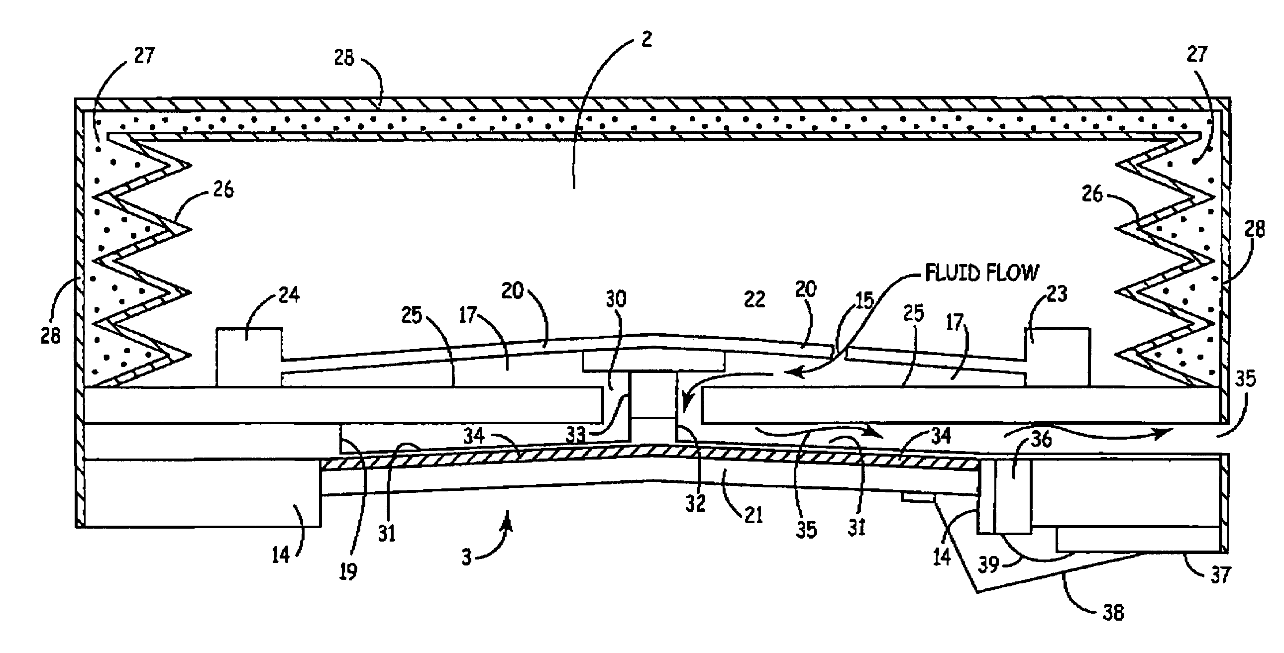
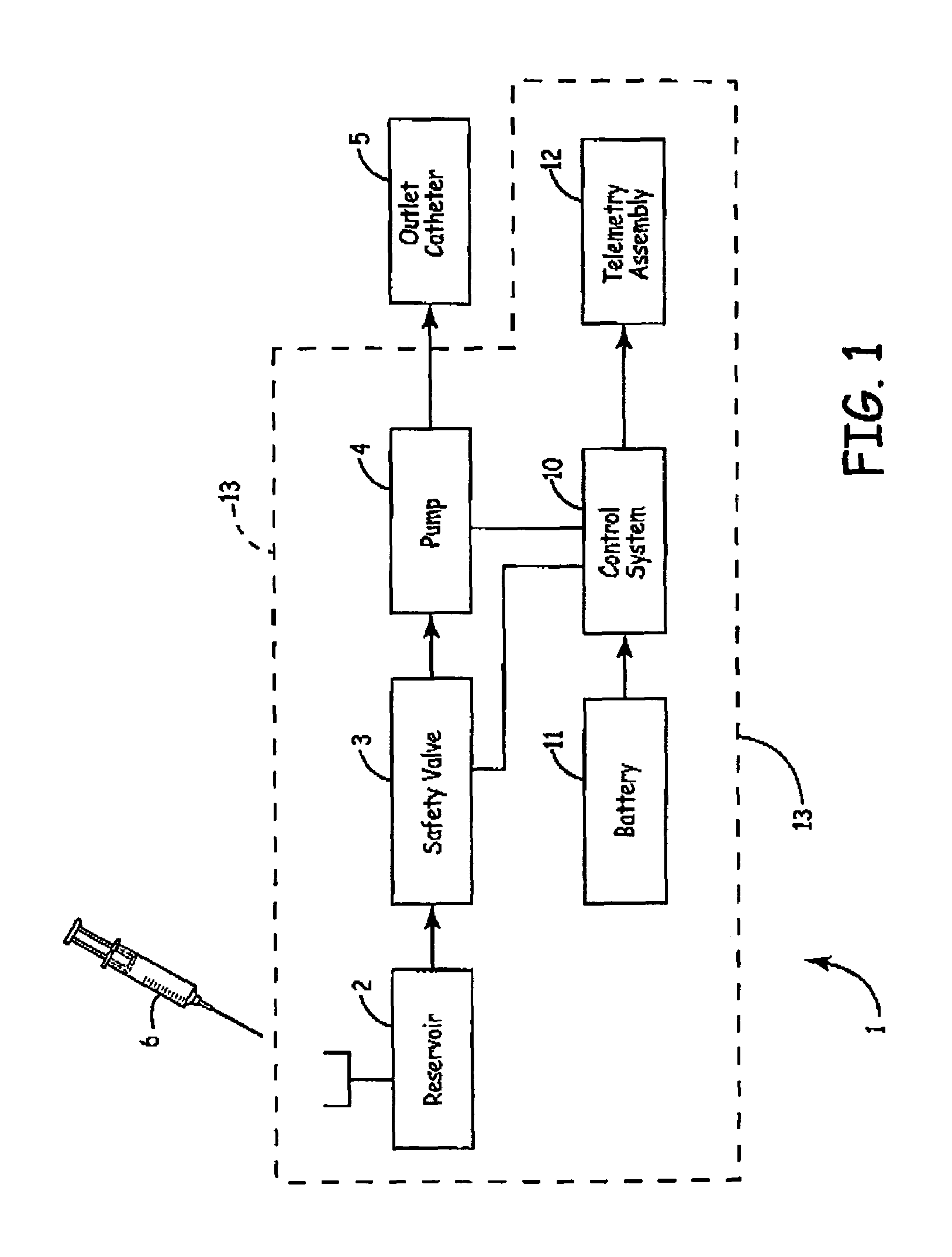
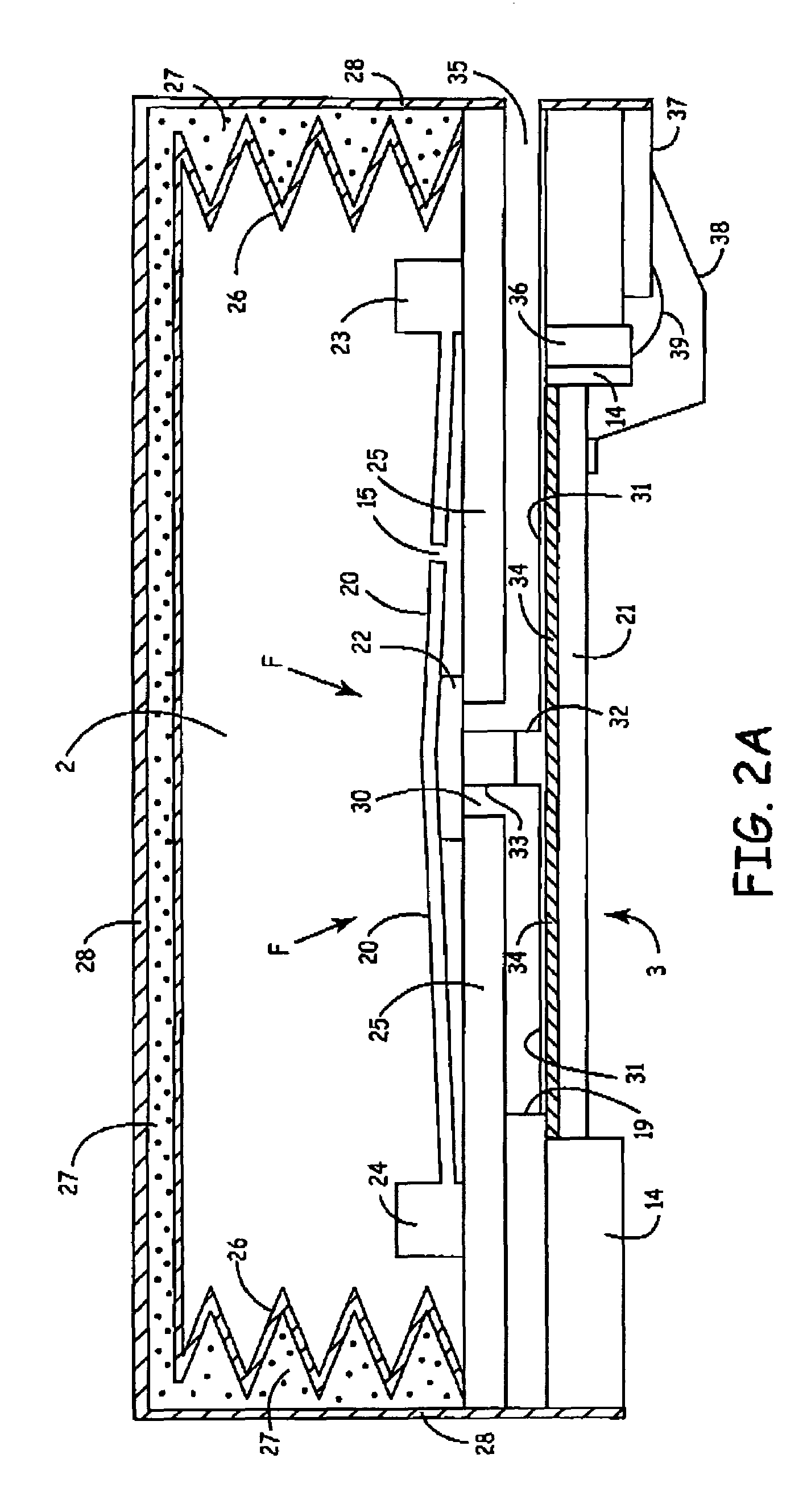
[0020]FIG. 1 shows a block diagram of the present invention. As seen, such a system 1 comprises a reservoir 2, safety valve assembly 3 assembly, pump 4, electronic controls 10, battery 11, telemetry assembly 12 and outlet catheter 5. Outlet catheter may be of any model desired and suited to the patient's requirements. Safety valve 3 assembly is coupled to the reservoir and also to pump 4. Pump may be of any suitable design, inclu...


PUM


Abstract

An implantable beneficial agent infusion device featuring a unique energy recovery circuit and a deflectable energy storing member such as a piezo-electric membrane is disclosed. The circuit and deflectable energy storing member cooperate to permit electrical energy employed to activate the member to be at least partially recovered. In a preferred embodiment, the deflectable energy storing member is connected to a seal which is opened to permit the delivery or infusion of a pre-determined amount of a beneficial agent to a patient when the member is deflected or actuated through the application of a sufficiently high voltage thereacross. Charge stored on or in the deflectable energy storing member as a result of the voltage being applied thereacross is recovered by a novel circuit when the deflectable energy storing membrane is permitted to return to its non-actuated state or position.

Description

RELATED APPLICATION[0001]This patent application is a continuation-in-part of U.S. patent application Ser. No. 09 / 017,195 to Haller et al. entitled “Implantable Drug Infusion Device Having a Safety Valve Assembly” filed Feb. 2, 1998 now abandoned and is also a continuation-in-part of U.S. patent application Ser. No. 09 / 494,530 to Haller et al. Entitled “Safety Valve Assembly for Implantable Beneficial Agent Infusion Device” filed Jan. 31, 2000 now U.S. Pat. No. 6,488,652. The disclosures of the foregoing patent applications are hereby incorporated by reference herein, each in its respective entirety.FIELD OF THE INVENTION[0002]The present invention relates to the field of implantable medical devices, and more particularly to an efficient drive circuit for a safety valve assembly for an implantable beneficial agent infusion device.BACKGROUND OF THE INVENTION[0003]Implantable drug infusion devices are used to provide patients with a constant and long term dosage or infusion of a drug ...

Claims


Application Information

Patent Timeline
IPC IPC(8): A61M37/00A61M5/142A61M5/145A61M5/168A61M31/00A61M39/22F15C5/00F16K99/00H10N30/80
CPCA61M5/14276H02N2/067A61M31/002F15C5/00F16K99/0001F16K99/0015F16K99/0048A61M39/22A61M2005/14513A61M2205/0244A61M2205/0294A61M2205/3523A61M2205/8212F16K2099/0088A61M5/16831
Inventor HALLER, MARKUSWEIJAND, KOEN J.
Owner MEDTRONIC INC
Learn More