
Reconfiguring a network by utilizing a predetermined length quiescent state

a network and quiescent state technology, applied in the field of reconfiguring a network of a computing system, can solve the problems of inconvenient subsystems relying on the monitoring system, and inability to meet the requirements of the monitoring system

Inactive Publication Date: 2006-06-27
TWITTER INC
View PDF16 Cites 113 Cited by
  • Summary
  • Abstract
  • Description
  • Claims
  • Application Information

AI Technical Summary

Benefits of technology

[0012]The reconfiguration capability of the present invention advantageously enables a network having a plurality of nodes to be reconfigured to reflect a change in topology of the network by utilizing a predetermined length quiescent state. In one embodiment, this predetermined period of time is sufficient to allow the transmission of reconfiguration requests from one node to other nodes of the network thereby causing the other nodes to also enter quiescent states. In another embodiment, this predetermined period of time is sufficient for protocols currently running on the network to complete execution. By utilizing this predetermined period of time, each node is able to exit from or terminate its quiescent state without having to check with or receive any communication from the other nodes of the network. Consequently, currently executing protocols are not interrupted and global synchronization is not required.

Problems solved by technology

However, the deactivation of the monitoring system greatly inconveniences the subsystems relying on the monitoring system.
Furthermore, global synchronization also detrimentally interrupts any protocols running when reconfiguration is initiated.
However, this procedure results in the danger of the transmission of messages from a node operating one configuration to nodes operating under another configuration, and because the contents of some messages are valid only when exchanged between nodes having the same view of the system, this procedure oftentimes leads to disastrous results.
In high availability systems, the above-mentioned disadvantages are unacceptable.

Method used


Image

  • Reconfiguring a network by utilizing a predetermined length quiescent state
  • Reconfiguring a network by utilizing a predetermined length quiescent state
  • Reconfiguring a network by utilizing a predetermined length quiescent state

Examples


Embodiment Construction

[0025]In accordance with the principles of the present invention, a network having a plurality of nodes is reconfigured to reflect a change in topology of the network by utilizing a predetermined length quiescent state. In one embodiment, this predetermined period of time is sufficient to allow the transmission of reconfiguration requests from one node to other nodes of the network thereby causing the other nodes to also enter quiescent states. In another embodiment, this predetermined period of time is sufficient for protocols currently running on the network to complete execution. By utilizing this predetermined period of time, each node is able to exit from or terminate its quiescent state without having to check with or receive any communication from the other nodes of the network.

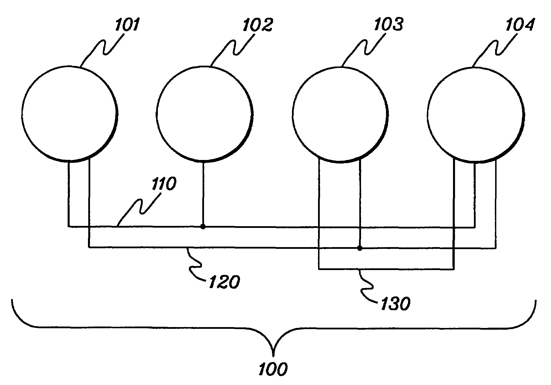
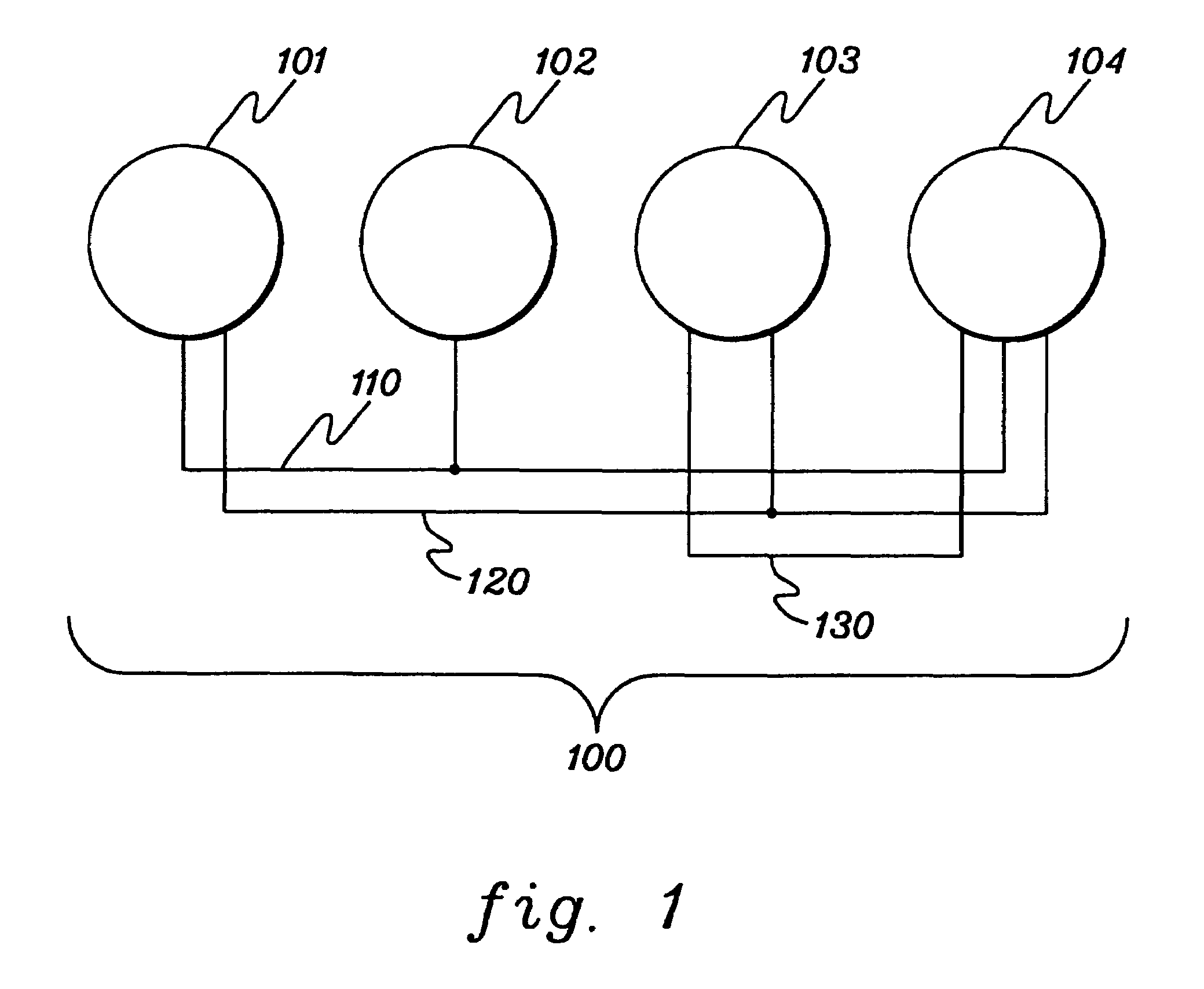
[0026]FIG. 1 depicts one example of a distributed computing system incorporating the reconfiguring capability of the present invention. In one embodiment, a distributed computing system 100 includes a ...


PUM


Abstract

A network having a plurality of nodes is reconfigured to reflect a change in topology of the network. In particular, upon receiving a reconfiguration request, each node enters a quiescent state for a predetermined period of time sufficient to allow at least one other node to also enter a quiescent state. Then, upon termination of the quiescent state, the node is reconfigured to reflect the change in the topology of the network without having to check with any other nodes of the network. In other embodiments, the predetermined period of time is sufficient to allow currently executing protocols to complete execution as well as to allow the transmission of reconfiguration requests for propagating reconfiguration in the network.

Description

TECHNICAL FIELD[0001]This invention relates, in general, to the reconfiguration of a network of a computing system. More particularly, this invention relates to reconfiguring a network having a plurality of nodes to reflect a change in topology of the network by utilizing a predetermined length quiescent state.BACKGROUND ART[0002]Typically, a distributed computing environment or computing system includes a number of processors or nodes interconnected to one another via one or more links to form a system of networks. This network of nodes is then able to process tasks concurrently in a manner which is more effective than with nodes processing individually.[0003]In order to allow the nodes of these computing systems to process tasks in such a manner, monitoring systems are implemented within the computing systems to monitor the status of the nodes and their network adapters. These monitoring systems typically monitor the computing system for the failure or activation of nodes within t...

Claims


Application Information

Patent Timeline
IPC IPC(8): G06F15/173
CPCH04L41/12H04L41/082H04L41/0816H04L12/12
Inventor CHANG, CHUN-SHIJURGENSEN, DENNIS D.KIRBY, ORVALLE T.KNOP, FELIPE
Owner TWITTER INC
Learn More