
Bendable needle for delivering bone graft material and method of use

Active Publication Date: 2006-06-27
WRIGHT MEDICAL TECH
View PDF11 Cites 287 Cited by
  • Summary
  • Abstract
  • Description
  • Claims
  • Application Information

AI Technical Summary

Benefits of technology

[0006]Accordingly, it is an object of the present invention to overcome the above mentioned disadvantages of the prior art by providing a bendable bone graft needle particularly useful in m

Problems solved by technology

Such needles have been unable to be precisely positioned, such as by bending.
Therefore, they have not been useful for ejecting bone graft towards hard to reach locations in the body.

Method used


Image

  • Bendable needle for delivering bone graft material and method of use
  • Bendable needle for delivering bone graft material and method of use
  • Bendable needle for delivering bone graft material and method of use

Examples


Embodiment Construction

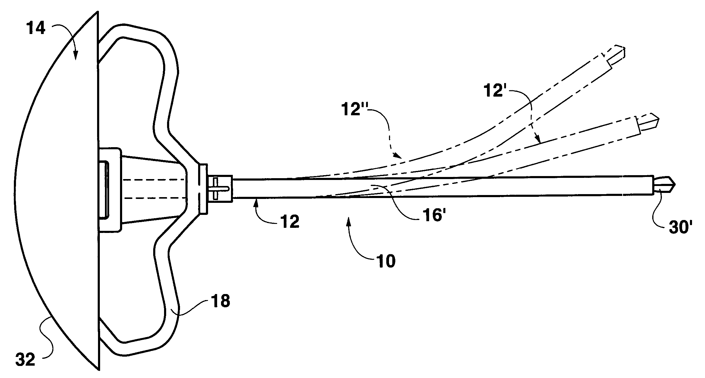
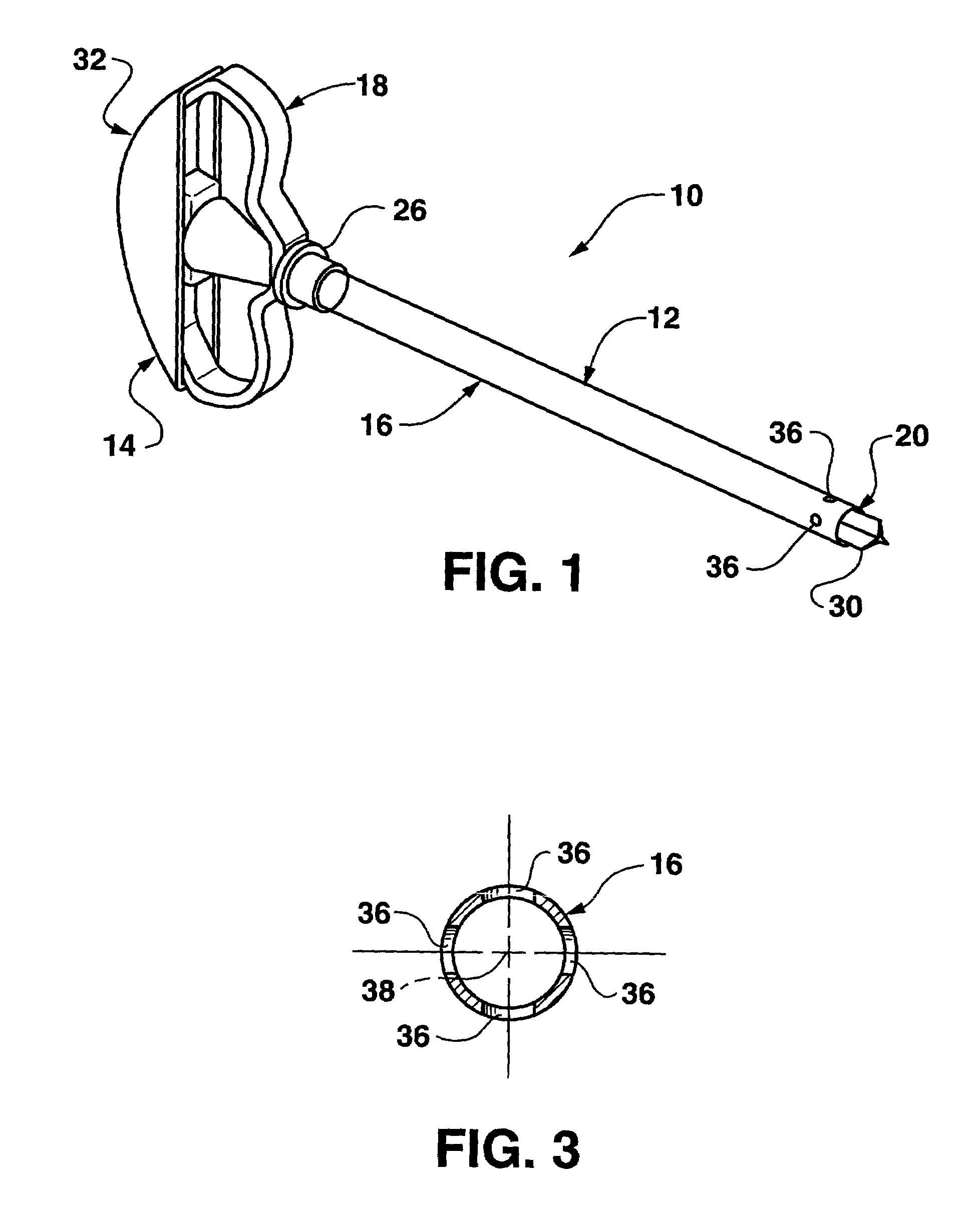
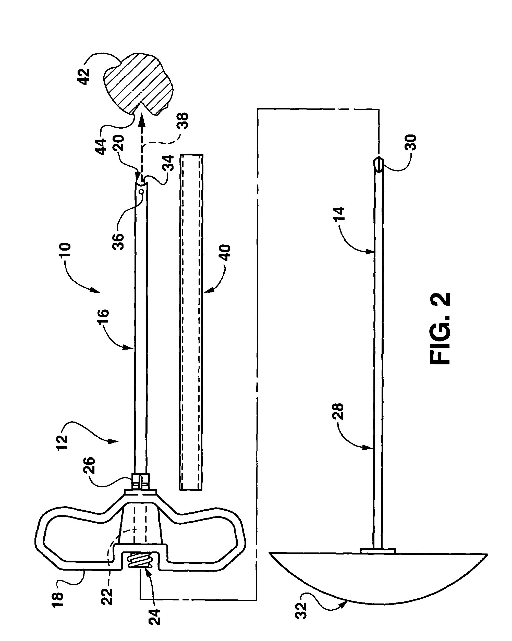
[0019]The present invention relates to a bone graft needle used to deliver bone graft material to a bone defect area in a patient's body in a minimally invasive procedure in which the bone defect area is accessed via a minimal portal or incision. FIGS. 1 and 2 illustrate an instrument assembly 10 comprising a bone graft needle 12 and a penetrating member 14, such as a trocar. The bone graft needle 12 comprises an elongate tubular delivery member 16 extending distally from a handle 18. The delivery member 16 has an open distal end 20 communicating with a longitudinal passage 22 extending entirely through the delivery member 16 and the handle 18. A hollow coupling 24 having open distal and proximal ends is disposed at a proximal end of passage 22 with the interior of the coupling 24 in communication with the passage 22. The coupling 24 is designed for releasable attachment to a standard syringe and may be designed as a conventional luer lock coupling. The handle 18 can have various co...


PUM


Abstract

A bone graft needle, particularly useful in minimally invasive procedures, is provided. The bone graft needle as well as its corresponding penetrating member may be made from bendable materials so that the combined instrument can more easily access hard to reach areas of the body.

Description

RELATED APPLICATIONS[0001]This application is related to Assignee's co-pending U.S. patent application Ser. No. 10 / 678,701, filed the same day as this patent application.BACKGROUND OF THE INVENTION[0002]1. Field of the Invention[0003]The present invention generally pertains to the use of graft materials for promoting bone growth and, more particularly, to ported needles for delivering bone graft materials to metaphyseal compression fractures, other bone voids or other bone defect areas.[0004]2. Discussion of the Prior Art[0005]In the past, bone graft materials have been delivered to bone defect areas, such as metaphyseal compression fractures or bone voids as well as other areas of bone structures having discontinuities, cavities, recesses or the like (hereinafter referred to as bone defect areas). Minimally invasive bone graft procedures are preferred in many cases, and the delivery or injection of bone graft material to the bone defect areas has been accomplished using a needle ha...

Claims


Application Information

Patent Timeline
IPC IPC(8): A61B17/58A61F2/00A61B10/00A61B10/02A61B17/00A61B17/16A61B17/34A61F2/28A61F2/46
CPCA61B17/1635A61B17/3468A61B10/025A61B17/00234A61B17/3472A61F2002/2892A61B2017/0046A61B2017/00969A61F2/4601A61F2002/2835A61B17/3478
Inventor TREACE, JOHN T.
Owner WRIGHT MEDICAL TECH
Learn More