
Vibrator, vibration unit, and vibrator control method

a technology of vibrator and control method, which is applied in the field of vibrator, vibration unit and vibrator control method, can solve the problems of cumbersome treating elements, weakening the strength to be exerted on the treatment subject portion, and cumbersome treating elements, so as to eliminate the difference in shifting range

Inactive Publication Date: 2006-06-27
OMRON HEALTHCARE CO LTD
View PDF8 Cites 9 Cited by
  • Summary
  • Abstract
  • Description
  • Claims
  • Application Information

AI Technical Summary

Benefits of technology

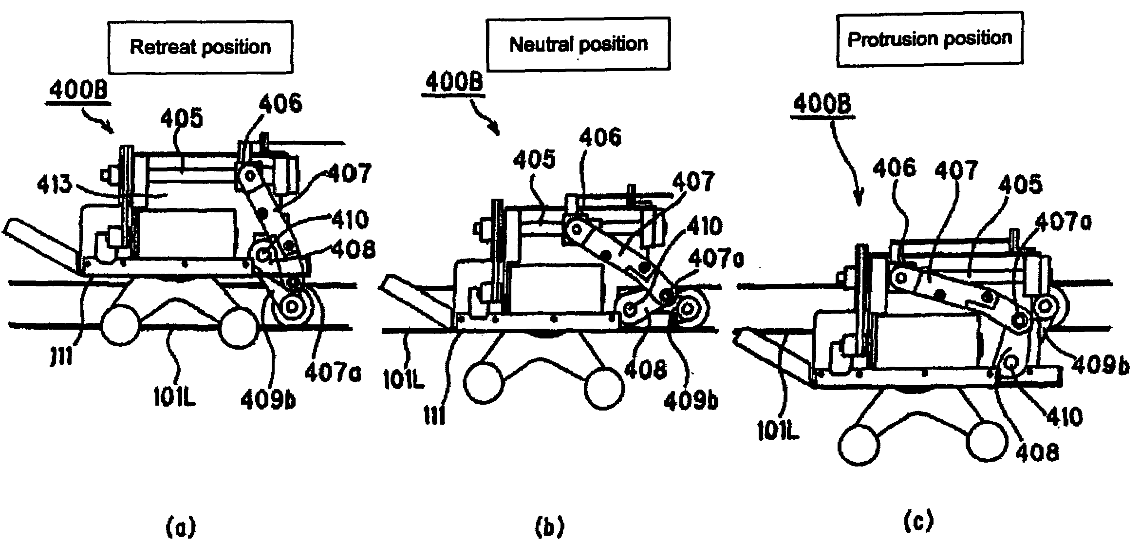
[0015]With this arrangement, it is possible to alter the position of the treating unit supported by the supporting means in a direction substantially orthogonal (or approximately perpendicular) to the shifting direction with respect to the guiding means. Since this arrangement does not change the position and orientation of the member for supporting the treating elements but changes the position of the treating unit itself which shifts along the guiding means, it is possible to form a position altering means without being limited by the driving structure of the treating elements, and consequently to ensure a greater amount of positional change. In other words, since it becomes possible to increase the range of a change in the amount of protrusion with respect to the treatment subject portion, the force to be exerted on the treatment subject portion is more properly controlled so that it is possible to achieve treatments with strength suitable for the condition and the corresponding portion. In other words, it is possible to achieve treatments with various functions.
[0018]By installing the treating elements having mutually different characteristics, it becomes possible to provide different treatments by using the respective pairs of the treating elements in a different manner, and consequently to provide treatments having various functions. In this case, the characteristics refer to characteristics such as mechanical properties including a shape, a material, an elastic property, etc., that can provide differences in sensitivity or treatment effects to the user.
[0027]In this manner, it is possible to form the orientation altering means without being limited by the driving structure of the treating elements not only when the position of the entire position of the treating unit is altered, but also when only the orientation of the treating unit is altered by changing only one portion of the position in the shifting direction of the guiding means. Therefore, by increasing the range of change of the amount of protrusion with respect to the treatment subject portion in the same manner, it becomes possible to control the force exerted on the treatment subject portion more properly and consequently to achieve treatments having strength suitable for the condition and the corresponding portion. If at least two pairs of right and left treating elements are placed in the shifting direction of the treating unit, switching can be made so as to cause the front or rear pair of treating elements in the shifting direction or both of the pairs to contact the treatment subject portion by altering the orientation of the treating elements with respect to the guiding means so that it becomes possible to carry out treatments having various functions.
[0042]Thus, the positions along the treatment subject portion of the first treating elements and the second treating elements placed longitudinally are altered at various positions during the shifting process along the treatment subject portion so that it is possible to eliminate a difference in shifting ranges along the treatment subject portion of the respective treating elements within a predetermined shifting range. Moreover, the treating elements to be made in contact with the treatment subject portion are switched by altering the positions of the first treating elements and second treating elements placed longitudinally in the treatment subject direction so that it becomes possible to achieve treatments having various functions. The vibrator is not limited to two pairs of the first treating elements and the second treating elements but may have more than two pairs of the treating elements.

Problems solved by technology

(1) Since the treating unit with treatment elements is caused to shift only along a guide, it is not possible to carry out treatments in accordance with the body shape of the user and, depending on positions of the treating unit, the treating elements tend to separate from the treatment subject portion, thereby weakening the strength to be exerted on the treatment subject portion, or the treating elements are too close to make the force exerting on the treatment subject portion too strong.
(2) When no treatments are being carried out, the treating elements form cumbersome objects.
(3) In general, since the distance between the treating elements and the human body is fixed, it is not possible to carry out treatments with a sufficient strength suitable for the condition and the corresponding portion. Although there are vibrators with which the distance between the treatment elements and the human body is adjustable, the amount of adjustment that can be made is small.
(4) It is not possible to achieve a stimulation-type work such as a finger-pressure therapy.
(5) Pounding stimulation onto the human body can be done only in a fixed operation direction and hence is monotonous.
(6) The number of treating elements that can be made to contact the human body is fixed, and this makes the stimulation monotonous.

Method used


Image

  • Vibrator, vibration unit, and vibrator control method
  • Vibrator, vibration unit, and vibrator control method
  • Vibrator, vibration unit, and vibrator control method

Examples


Embodiment Construction

[0086]Some embodiments of the invention are described next with reference to drawings.

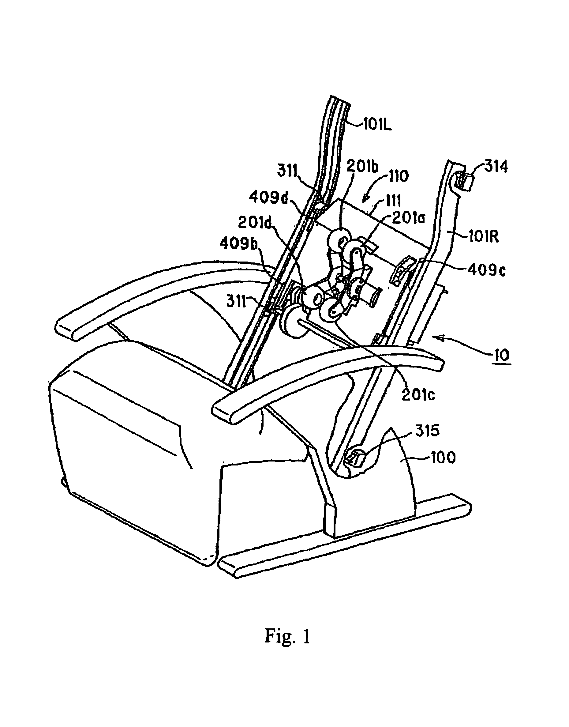
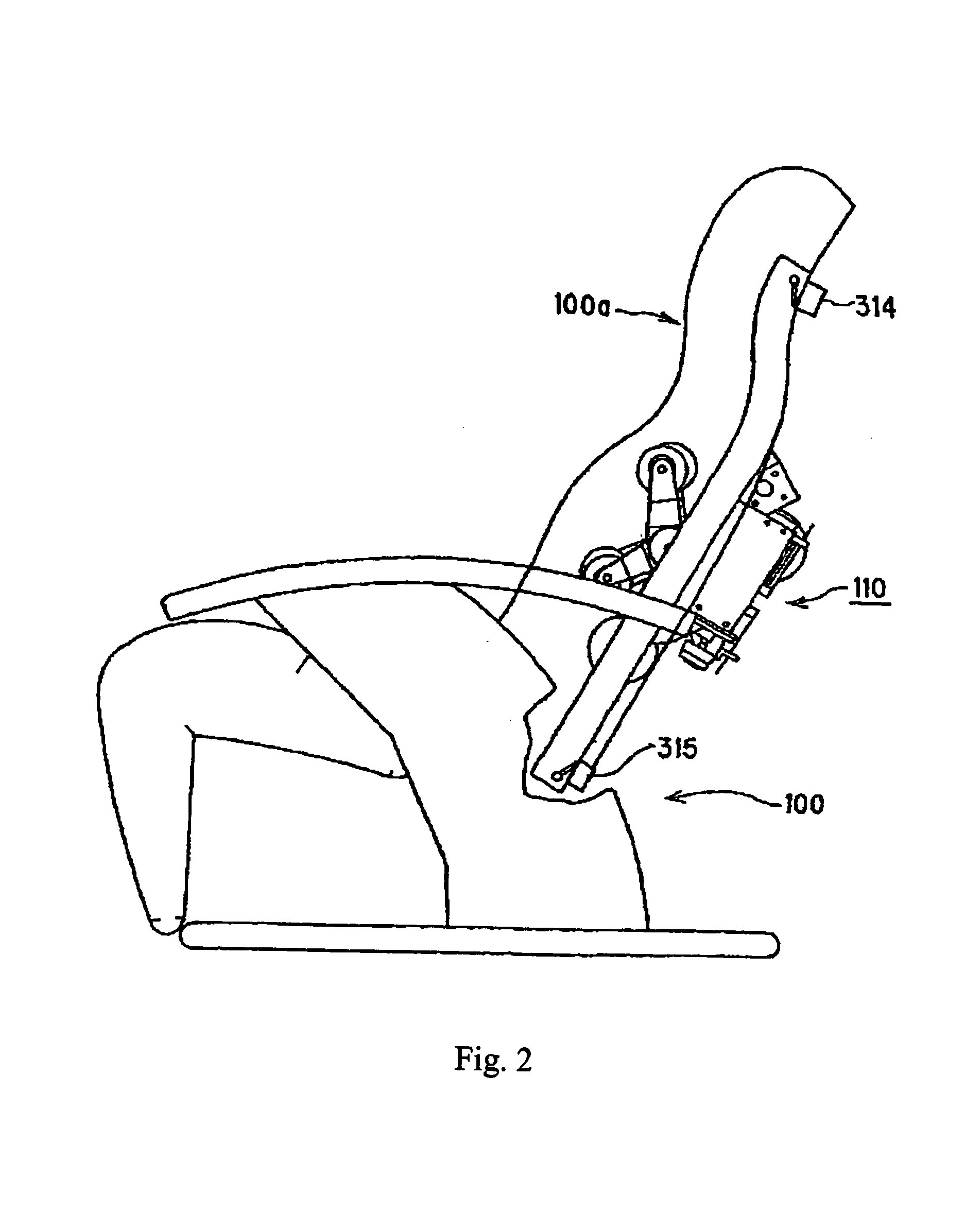
[0087]FIG. 1 is a perspective view that schematically shows the structure of a vibrator 10 in accordance with a preferred embodiment of the invention. In FIG. 1, a cover sheet and a cushion of a back portion 100a are omitted from the drawing. FIG. 2 is a side view showing the entire portion of the vibrator 10, and this drawing shows the outer shape and the inner structure of the back portion 100a.

[0088]The vibrator 10 is constituted by the back portion 100a of a freely reclining chair 100 in which a treating unit 110 is combined. Massaging balls (treating elements) 201a to 201d, which are placed so as to protrude toward the surface side covered with a cover sheet of the back portion 100a from the treating unit 110, carry out massaging treatments on the human body. The massaging balls include a pair of right and left massaging balls 201a, 201b (first treating elements) placed on an upper side along...


PUM


Abstract

A vibrator has massaging balls supported by a treating unit that may be shifted along a subject portion for treatment, guided by guiding members. The treating unit is supported by a supporting structure with respect to the guiding members. A position or orientation altering mechanism is provided for altering the position of the treatment unit in a direction orthogonal to the direction of its shifting or the orientation of the treating unit with respect to the guiding members. The supporting structure may include an engaging unit that engages the guiding members and an arm for supporting the engaging unit.

Description

[0001]This application is a continuation of International Application No. PCT / JP01 / 05672, filed Jun. 29, 2001, which claims priority based on Japanese Patent Applications 2000-199599 filed Jun. 30, 2000 and 2000-344502 filed Nov. 10, 2000.FIELD OF THE INVENTION[0002]This invention relates to a vibrator, a vibration unit and a vibrator control method, which carry out treatments on the human body by driving treating elements.BACKGROUND OF THE INVENTION[0003]Japanese Patent Publication Tokukou-Hei 1-49496 discloses, as an example of conventional vibrator of this type, a vibrator in which an arm having a pair of treating elements is swingably driven around a main shaft to carry out massaging treatment with the intensity being changed by changing the angle of the arm around the main shaft.[0004]Japanese Utility Model Publication Jikkai-Shou 56-125232 discloses a vibrator in which a pair of massaging rings is swingably attached eccentrically to a first rotation shaft in a tilted manner, a...

Claims


Application Information

Patent Timeline
Patent Type & Authority Patents(United States)
IPC IPC(8): A61H15/00A61H1/00A61H37/00
CPCA61H15/0078A61H7/007A61H2015/0028A61H2201/0138A61H2201/0149A61H2201/1654A61H2205/081A61H2201/1427A61H2201/1623A61H2201/1669
Inventor MORI, KENTAROMIKI, AKITOSHITANAKA, KOICHITAKAHASHI, KUNIYOSHI
Owner OMRON HEALTHCARE CO LTD
Learn More