Discharge lamp operating apparatus and self-ballasted electrodeless discharge lamp

Inactive Publication Date: 2006-06-20
PANASONIC CORP
View PDF22 Cites 3 Cited by
  • Summary
  • Abstract
  • Description
  • Claims
  • Application Information

AI Technical Summary

Benefits of technology

[0018]Therefore, with the foregoing in mind, it is a main object of the present invention to provide a discharge lamp operating apparatus with a simple structure that can operate a fluorescent lamp reliably.
[0027]According to the present invention, the control terminal driving circuit includes a series circuit of a voltage clamp element and an impedance element that is connected to at least one end of a drive winding, so that a discharge lamp operating apparatus that can operate a fluorescent lamp reliably can be realized simply by adding the impedance element. When the discharge lamp operating apparatus of the present invention is a self-ballasted electrodeless discharge lamp, it is necessary to reduce the discrepancy between the resonant frequency of the resonant load circuit and the on / off frequency of the inverter circuit, and therefore the present invention provides a larger advantage.

Problems solved by technology

Furthermore, it was also found that in the case of the fluorescent lamp 8 having electrodes, this structure was not sufficient to operate the fluorescent lamp 8 reliably in any environment.
On the other hand, adding significant changes to the structure of the operating apparatus for operating the fluorescent lamp 8 results in an increase of the cost of products, and it is also necessary to examine the structure with the added changes carefully whether or not any new problem may be caused.

Method used


Image

  • Discharge lamp operating apparatus and self-ballasted electrodeless discharge lamp
  • Discharge lamp operating apparatus and self-ballasted electrodeless discharge lamp
  • Discharge lamp operating apparatus and self-ballasted electrodeless discharge lamp

Examples


embodiment 1

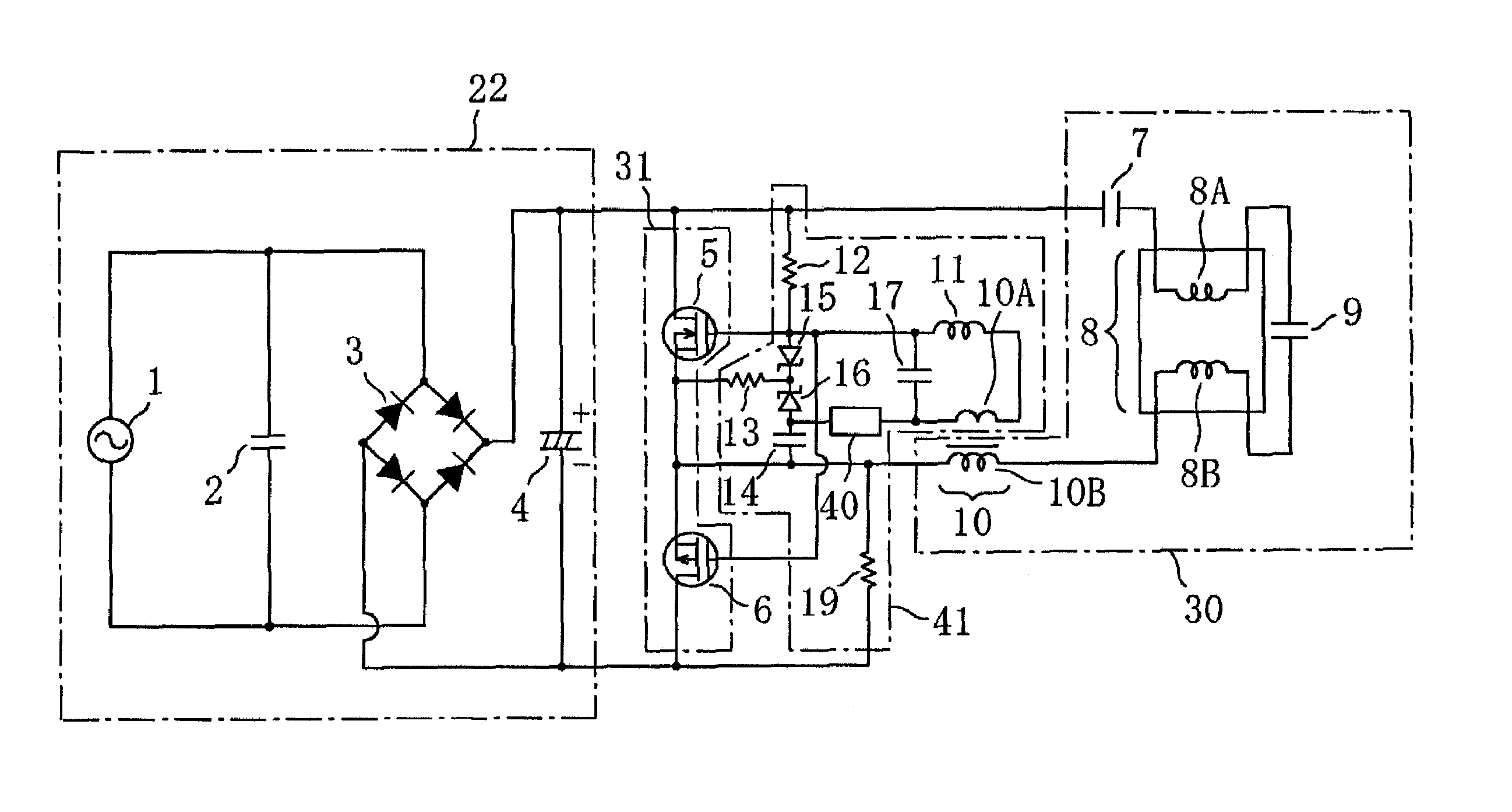
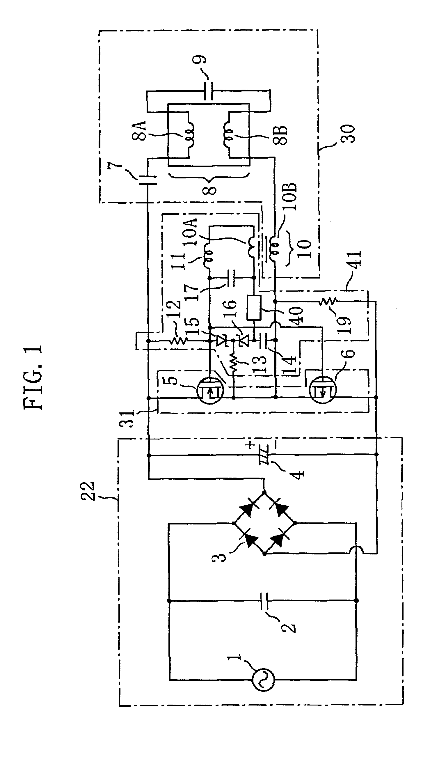
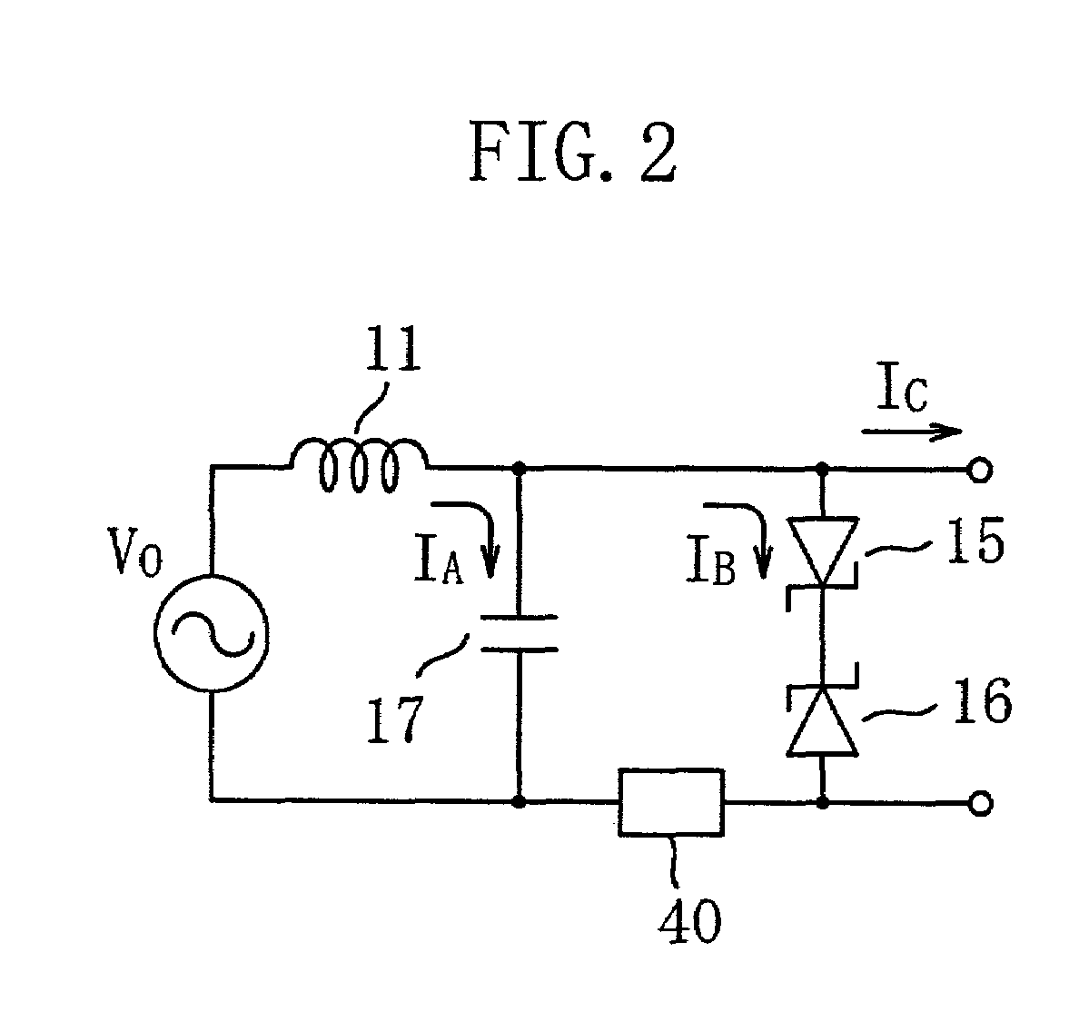
[0046]A discharge lamp operating apparatus of Embodiment 1 of the present invention will be described with reference to FIGS. 1 and 2. FIG. 1 schematically shows the structure of the discharge lamp operating apparatus of this embodiment.

[0047]The discharge lamp operating apparatus of this embodiment includes a DC power circuit portion 22 that outputs a DC voltage, an inverter circuit 31 including switching elements provided with control terminals (5 and 6) that converts the output from the DC power circuit portion 22 to an AC voltage, a control terminal driving circuit 41 for controlling the switching elements provided with control terminals (5 and 6) to be on or off, and a resonant load circuit 30. The resonant load circuit includes a discharge lamp 8, a first inductor 10B, and a first capacitor 7 and a capacitor 9.

[0048]The control terminal driving circuit 41 includes a series circuit of a drive winding 10A mutually coupled to a first inductor 10B, voltage clamp elements (15 and 1...

embodiment 2

[0064]Next, a discharge lamp operating apparatus of Embodiment 2 of the present invention will be described with reference to FIGS. 5 and 6. The discharge lamp operating apparatus of this embodiment is an operating apparatus for an electrodeless discharge lamp having no electrodes as a discharge lamp. FIG. 4 is a schematic circuit diagram showing the structure of this embodiment.

[0065]The DC power circuit portion 22 and the inverter circuit 31 in the discharge lamp operating apparatus shown in FIG. 4 have the same structures as in Embodiment 1 as above. Similarly to Embodiment 1, a resistor 50, which is an impedance element, is inserted in series with the Zener diodes 15 and 16, which are voltage clamp elements, in the control terminal driving circuit 56 of this embodiment. Other aspects in the control terminal driving circuit 56 have the same structures in those of the control terminal driving circuit 23 shown in FIG. 6.

[0066]The discharge lamp operating apparatus of this embodimen...


PUM


Abstract

A discharge lamp operating apparatus includes a DC power circuit portion for outputting a DC voltage; an inverter circuit including a switching element provided with a control terminal for converting an output from the DC power circuit portion to an AC voltage; a control terminal driving circuit for controlling the switching element provided with a control terminal to be on or off; and a resonant load circuit including a discharge lamp, a first inductor and a first capacitor. The control terminal driving circuit includes a drive winding mutually coupled to the first inductor; a series circuit of a voltage clamp element and an impedance element, the series circuit being connected to at least one end of the drive winding, and the control terminal driving circuit is configured to control the switching element provided with a control terminal to be on or off by a voltage generated at the drive winding.

Description

BACKGROUND OF THE INVENTION[0001]The present invention relates to an operating apparatus for operating a discharge lamp (discharge lamp operating apparatus) and a self-ballasted electrodeless discharge lamp.[0002]In recent years, as discharge lamp operating apparatuses, electronically operating apparatuses (inverter) are widely used in view of improvement of luminous efficiency, and compactness and lightness of an apparatus. Examples of such a discharge lamp operating apparatus are disclosed in Japanese Laid-Open Patent Publication Nos. 10-162983 and 2000-353598. The conventional discharge lamp operating apparatuses will be described below.[0003]FIG. 6 shows the structure of the discharge lamp operating apparatus disclosed in Japanese Laid-Open Patent Publication No. 2000-353598. The discharge lamp operating apparatus shown in FIG. 6 includes a DC power 22, an inverter circuit 31, a control terminal driving circuit 23, and a resonant load circuit 30 including a fluorescent lamp 8.[0...

Claims


Application Information

Patent Timeline
IPC IPC(8): H05B37/02H05B41/282H05B41/392
CPCH05B41/2825H05B41/3925H05B41/2827Y02B20/185Y02B20/00
Inventor MIYAZAKI, KOUJIKURACHI, TOSHIAKIKAWASAKI, MITSUHARU
Owner PANASONIC CORP
Why Eureka
Try Eureka