
Method of and apparatus for transferring articles from a first position to a second position

a technology of transferring apparatus and transferring method, which is applied in the direction of gearing, mechanical control devices, instruments, etc., can solve the problems of difficult to achieve added requirements and more subjected mechanisms, and achieve the effect of minimal backlash, improved parallel linkage, and minimal backlash

Inactive Publication Date: 2006-06-20
OWENS-BROCKWAY GLASS CONTAINER INC
View PDF11 Cites 11 Cited by
  • Summary
  • Abstract
  • Description
  • Claims
  • Application Information

AI Technical Summary

Benefits of technology

The present invention provides a takeout mechanism that can transfer articles from one position to another without changing their orientation. The mechanism is designed to withstand high temperatures and is particularly suitable for use in glass container forming machines. It is powered by a reversible a.c. servo motor for precise control over operating speeds and operates with minimal backlash. The mechanism includes a parallel motion mechanism to ensure the axes of the articles do not change during the transfer step. It is also equipped with spring-mounted rollers to ensure close engagement between the drive and driven gears, regardless of wear and tear during normal operation. Overall, the takeout mechanism of the present invention is resistant to elevated temperatures, can operate for a prolonged duration with minimal backlash, and is particularly suitable for use in glass container forming machines.

Problems solved by technology

This mechanism superceded chain driven parallel motion mechanisms, such as that of the aforesaid '973 patent, because chain driven mechanisms were more subject to wear than the belt driven mechanisms that replaced them.
These increased machine speeds require shorter container transfer times, with more precise control of acceleration and deceleration motions and with zero or near zero backlash in the operation of the oscillating takeout arm, and these added requirements have been difficult to achieve with reinforced belt or chain driven parallel motion mechanisms.

Method used


Image

  • Method of and apparatus for transferring articles from a first position to a second position
  • Method of and apparatus for transferring articles from a first position to a second position
  • Method of and apparatus for transferring articles from a first position to a second position

Examples


Embodiment Construction

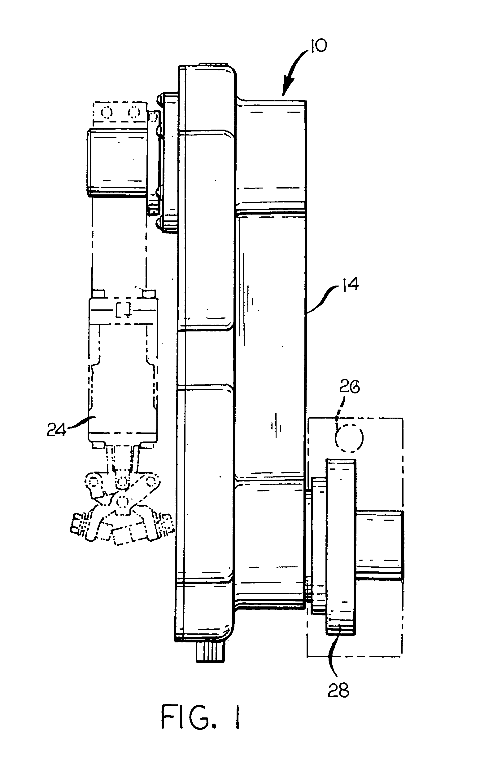
[0015]A takeout arm assembly according to the preferred embodiment of the present invention is indicated generally by reference number 10 in the drawing. The takeout assembly 10 includes a fixed shaft 12, which corresponds in function to the shaft 18 of the aforesaid '973 patent.

[0016]A multi-piece housing 14 is journalled on the shaft 12 to be oscillatible with respect to the shaft 12. Located within the housing 14 is a gear 16 with a plurality of teeth around its periphery. The gear 16 is also oscillatible with the housing 14. A second gear 18, which is spaced from the gear 16 and whose central axis is parallel to that of the gear 16, is also located within the housing 14. The gear 18 is co-axially secured to a shaft 20, which corresponds in function to the shaft 23 of the '973 patent, and the second gear 18 and the shaft 20 are caused to oscillate with the gear 16 under power from a reciprocating rack 30, as will be hereinafter explained more fully.

[0017]A bearing 22 is mounted w...


PUM

PropertyMeasurementUnit
temperatureaaaaaaaaaa
temperaturesaaaaaaaaaa

Abstract

A takeout arm assembly (10) for an I.S. glass container forming machine, the arm assembly having a housing (14) that is oscillatible about the central axis of a first shaft (12). The housing has a first gear (16) that is coaxial with the first shaft and oscillatible with the housing, and with respect to the first shaft, the housing further having a second gear (18) that is positioned within and is rotatable with respect to the housing. The second gear is spaced from the first gear with the axes of the first and second gears being parallel to one another. A rack (30) having teeth in engagement with teeth on the first gear and the second gear is caused to move rectilinearly by oscillating motion of a reversible a.c. servo motor (26) that serves to drive the first gear, to thereby transmit turning motion from the first gear to the second gear. The rack is resiliently biased into engagement with the first gear and the second gear by spaced, spring-mounted rollers (36, 38) that rollingly engage the rack on a side opposed to the tooth side of the rack and in alignment with the first gear and the second gear, respectively.

Description

FIELD OF THE INVENTION[0001]This invention relates to a method of and an apparatus for transferring articles from a first position to a second position by a pivoting motion that does not change the angular orientation of the articles during transfer. More particularly, this invention relates to a method and an apparatus of the aforesaid character for sequentially transferring freshly-formed glass containers one or more at a time from a blow molding position of a glass container forming machine of the individual section (I.S.) type to a deadplate of the machine to begin cooling while awaiting further transfer to a removal conveyor.BACKGROUND OF THE INVENTION[0002]As is explained, for example, in commonly assigned U.S. Pat. No. 6,076,654 (Leidy) and U.S. Pat. No. 6,241,448 B1 (Nicholas), the disclosure of each of which is incorporated by reference herein, or as is otherwise known, most glass containers are manufactured by a machine type known as an I.S. machine. Containers are manufac...

Claims


Application Information

Patent Timeline
Patent Type & Authority Patents(United States)
IPC IPC(8): B25J18/04
CPCB25J9/102C03B9/447Y10T74/19819Y10T74/20305
Inventor DIFRANK, FRANK J.SHUE, LARRY N.KIRKMAN, THOMAS R.
Owner OWENS-BROCKWAY GLASS CONTAINER INC
Learn More