
Dual chamber side airbag apparatus and method

a side impact airbag and dual chamber technology, which is applied in the direction of pedestrian/occupant safety arrangement, vehicular safety arrangement, vehicle components, etc., can solve the problems of inability to easily adapt difficulty in installing inflators, and inability to easily use different airbag configurations. , to achieve the effect of reducing manufacturing and installation costs and facilitating adaptability to different vehicle configurations

Inactive Publication Date: 2006-06-20
AUTOLIV ASP INC
View PDF19 Cites 45 Cited by
  • Summary
  • Abstract
  • Description
  • Claims
  • Application Information

AI Technical Summary

Benefits of technology

[0009]The apparatus of the present invention has been developed in response to the present state of the art, and in particular, in response to the problems and needs in the art that have not yet been fully solved by currently available airbag systems. Thus, it is an overall objective of the present invention to provide an airbag system and related methods that provide multiple inflation pressures and easy adaptability to different vehicle configurations with a minimum of manufacturing and installation cost.
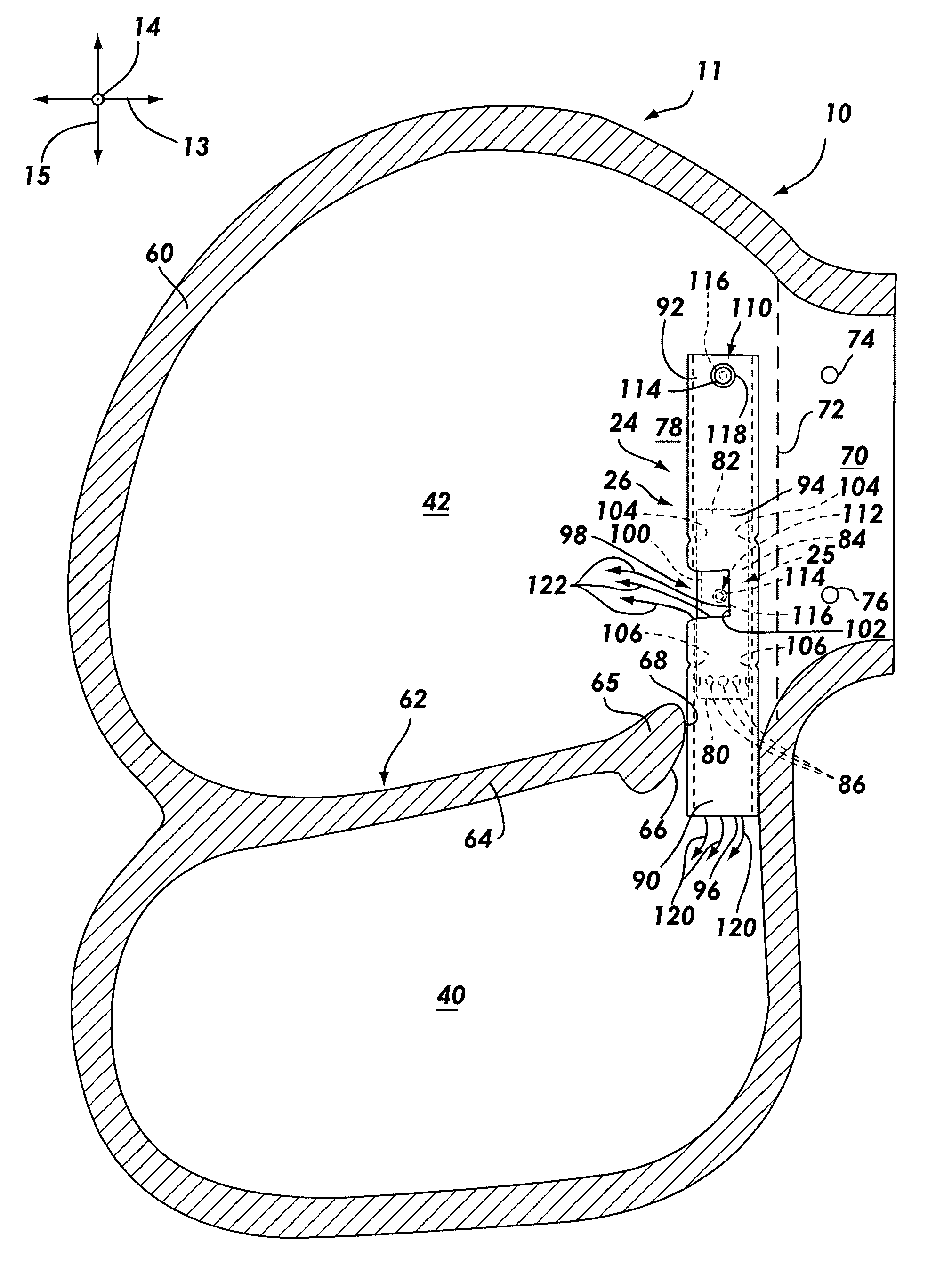
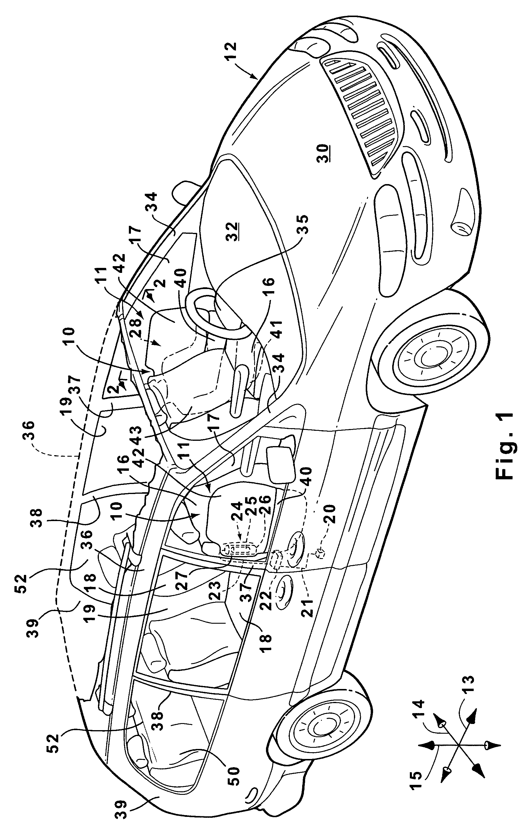
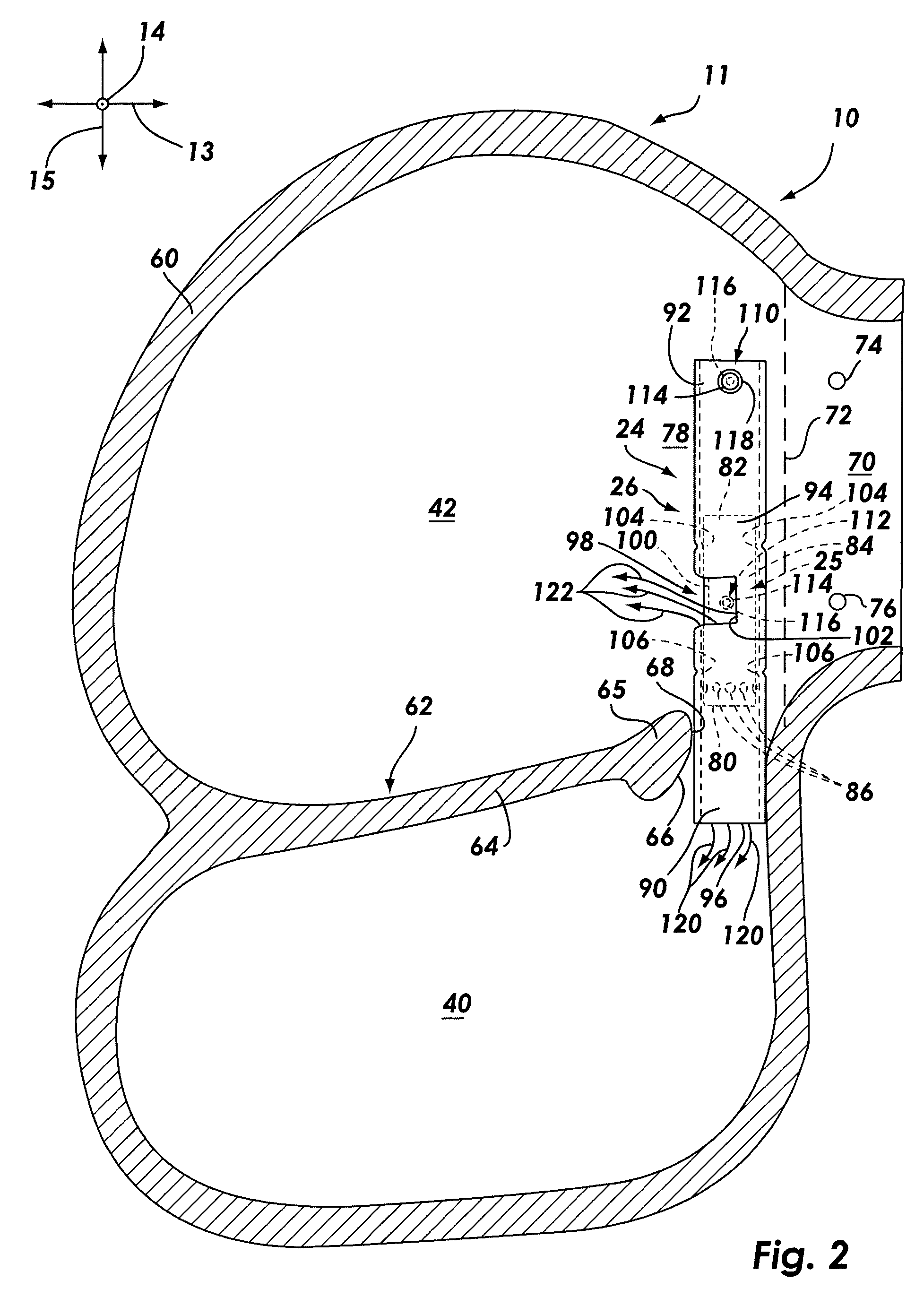
[0011]The cushion has a pelvic chamber and a thoracic chamber disposed generally above the pelvic chamber. The pelvic chamber inflates beside the pelvis of the occupant to protect the pelvis from lateral impact. Similarly, the thoracic chamber inflates beside the thorax of the occupant to protect the thorax from lateral impact.
[0019]The first flow moves directly toward the first aperture, and soon passes the first end of the inflator. The first flow is then able to flow through the entire inside diameter of the housing and exit the first aperture at a comparatively high flow rate. The second flow moves toward the second aperture and flows in the generally annular space between the inflator and the inside diameter of the housing. The second flow then exits the second aperture at a comparatively lower flow rate. The flow rate ratio between the first and second flows causes the pelvic chamber to inflate to a higher pressure than that of the thoracic chamber. Thus, the pelvic chamber is able to resist the comparatively higher momentum of the pelvis, and the thoracic chamber is able to more gently cushion the more sensitive thorax.
[0020]The airbag module may be easily assembled. The first and second fasteners may be installed through the port of the housing and the second aperture, respectively, and welded in place so that the studs protrude outward from the housing. The inflator may then be inserted into the housing through either end, such that the first and second retention ridges grip the inflator, thus forming the inflation assembly.
[0022]The ratio of gases flowing into the pelvic and thoracic chambers may be easily altered by axially adjusting the position of the inflator within the housing. Readjustment of the inflator such that the outlet orifices are closer to the second aperture shortens the path through which the second flow must pass, and lengthens the path through which the first flow must pass. Thus, the flow rate of the second flow is increased and the flow rate of the first flow is decreased to increase the pressure of the thoracic chamber relative to that of the pelvic chamber. Similarly, readjustment of the inflator in the opposite direction increases the pressure of the pelvic chamber relative to that of the thoracic chamber. Thus, the inflation assembly may easily be adjusted to suit different cushions, occupants, or vehicles.
[0025]Through the use of the airbag assembly and related methods of the present invention, cost savings may be obtained through the use of common inflation assembly parts for multiple different airbag systems. Additionally, two different inflation pressures may be provided within a single cushion without requiring expensive mounting or gas delivery hardware. As a result, the availability and effectiveness of vehicular airbag systems may be enhanced.

Problems solved by technology

Unfortunately, many known airbags, including seat mounted side impact airbags, are only able to inflate to one comparatively uniform pressure level.
Hence, a part of the occupant's body may be subject to impact protection that is either too rigid or too soft.
More precisely, some such airbag systems have inflators that are somewhat difficult to install in the airbag cushion.
Some known systems utilize inflators that are somewhat inflexible in their positioning in the cushion or in the vehicle, and thus cannot readily be used for different airbag configurations.
Furthermore, some such airbag systems require the use of snorkels or other comparatively expensive hardware to distribute the gas within the cushion.
Yet further, many such systems do not permit easy adaptation of the ratio of gas that flows into the various portions of the cushion, and are thus difficult to adapt for use in multiple vehicle configurations.

Method used


Image

  • Dual chamber side airbag apparatus and method
  • Dual chamber side airbag apparatus and method
  • Dual chamber side airbag apparatus and method

Examples


Embodiment Construction

[0033]The presently preferred embodiments of the present invention will be best understood by reference to the drawings, wherein like parts are designated by like numerals throughout. It will be readily understood that the components of the present invention, as generally described and illustrated in the figures herein, could be arranged and designed in a wide variety of different configurations. Thus, the following more detailed description of the embodiments of the apparatus, system, and method of the present invention, as represented in FIGS. 1 through 5, is not intended to limit the scope of the invention, as claimed, but is merely representative of presently preferred embodiments of the invention.

[0034]The present invention utilizes principles of gas flow resistance to enable inflation gas to be effectively delivered to multiple chambers of a cushion to provide different inflation pressures. Furthermore, the present invention uses parts that can be assembled in multiple ways to...


PUM


Abstract

An airbag module is disclosed which, in one configuration, inflates from a vehicle seat to protect a vehicle occupant against lateral impact. The airbag module has a cushion with a pelvic chamber and a thoracic chamber. The airbag module also has an inflation assembly including an inflator within a housing inside the cushion. The housing has an aperture disposed within each of the chambers such that, when the inflator deploys, the pelvic chamber is inflated to a relatively higher pressure. The inflator may be moved axially within the housing to control the pressure ratio between the chambers. The housing is attached to the vehicle seat via attachment features that may be located at a variety of positions with respect to the remainder of the housing to facilitate adaptation of the inflation assembly to multiple cushion and vehicle configurations.

Description

BACKGROUND OF THE INVENTION[0001]1. Field of the Invention[0002]The present invention relates to systems and methods for protecting vehicle occupants from injury. More specifically, the present invention relates to a side impact airbag with two chambers that can be inflated to different pressures.[0003]2. Description of Related Art[0004]The inclusion of inflatable safety restraint devices, or airbags, is now a legal requirement for many new vehicles. Airbags are typically installed in the steering wheel and in the dashboard on the passenger side of a car. In the event of an accident, an accelerometer within the vehicle measures the abnormal deceleration and triggers the expulsion of rapidly expanding gases from an inflator. The expanding gases fill the airbags, which immediately inflate in front of the driver and passenger to protect them from impact against the windshield.[0005]Side impact airbags such as inflatable curtains and seat mounted airbags have also been developed in resp...

Claims


Application Information

Patent Timeline
Patent Type & Authority Patents(United States)
IPC IPC(8): B60R21/207B60R21/233B60R21/231B60R21/26
CPCB60R21/26B60R21/23138B60R21/207B60R2021/23316
Inventor STEIMKE, DANIEL L.LIGHTHALL, BRIAN M.
Owner AUTOLIV ASP INC
Learn More