
Method for effectively diagnosing the operational state of a variable valve lift device

Active Publication Date: 2006-06-20
DELPHI TECH IP LTD
View PDF7 Cites 73 Cited by
  • Summary
  • Abstract
  • Description
  • Claims
  • Application Information

AI Technical Summary

Benefits of technology

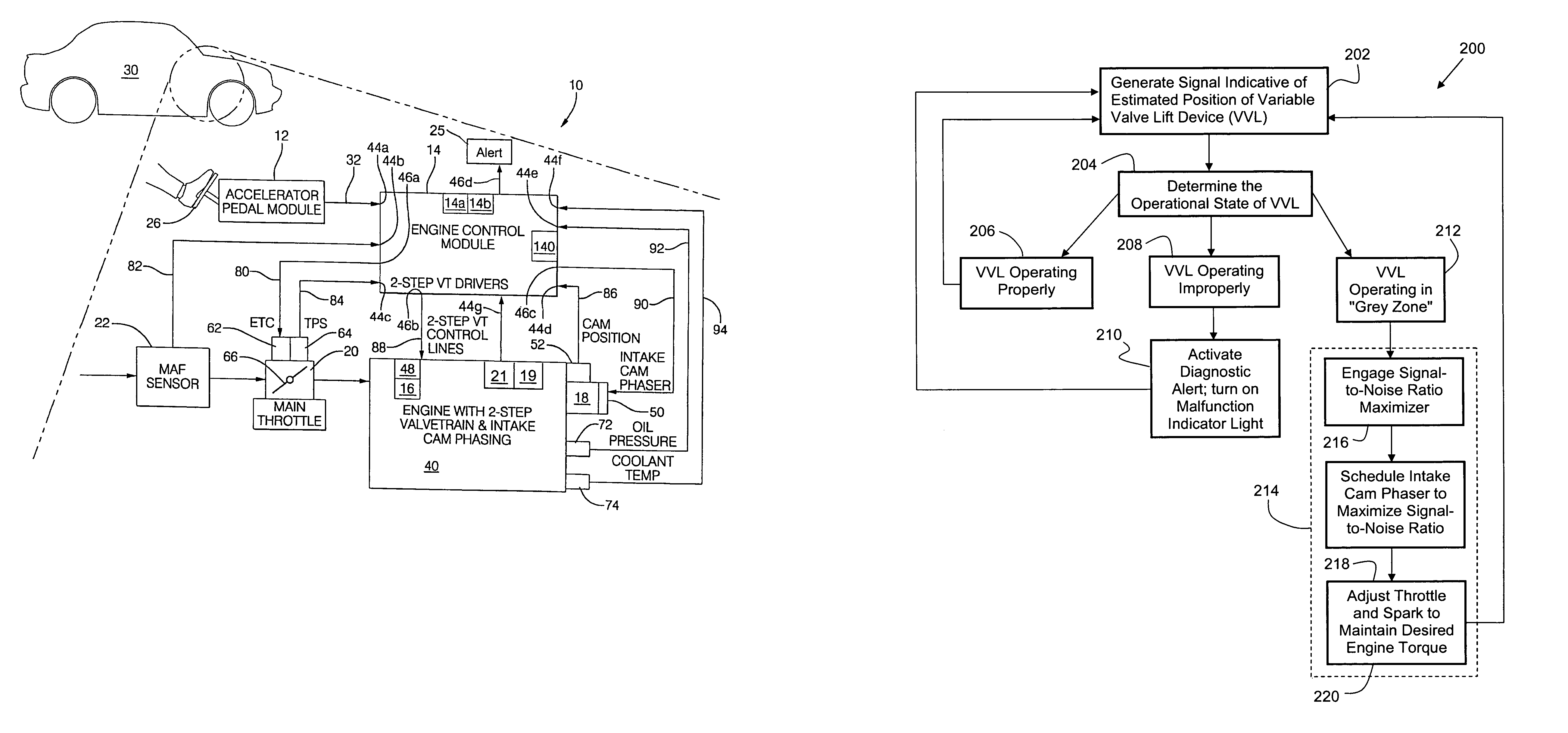
[0009]The method of the present invention includes adjusting the camshaft phase angle from what was originally considered to be an optimal position for torque, power, NOX, and fuel economy, across a range of alternate camshaft phase angle positions to identify a unique camshaft phase angle that increases and maximizes the signal strength of the signal indicative of the position of the variable valve lift device, thereby increasing the signal-to-noise ratio so that the signal can more reliably indicate the operational state of the variable valve lift device. The unique cam phase angle may be obtained using a pre-determined look-up table that is dependant upon the current operating conditions of the engine. By re-positioning the camshaft to a phase angle relative to a crankshaft to maximize the signal-to-noise ratio, a higher degree of certainty and reliability is achieved when diagnosing the operational state of the two-step variable valve lift device.

Problems solved by technology

This uncertain diagnostic condition (i.e., grey-zone) detected by the engine's diagnostic system may be caused by a high level of background or ambient noise, which results in a low signal-to-noise ratio.
The low signal-to-noise ratio in turn makes it difficult for the engine's diagnostic system to extract a meaningful signal representing the measured parameter associated with the engine cylinder, and thereby determine the operational state of the variable valve lift device.

Method used


Image

  • Method for effectively diagnosing the operational state of a variable valve lift device
  • Method for effectively diagnosing the operational state of a variable valve lift device
  • Method for effectively diagnosing the operational state of a variable valve lift device

Examples


Embodiment Construction

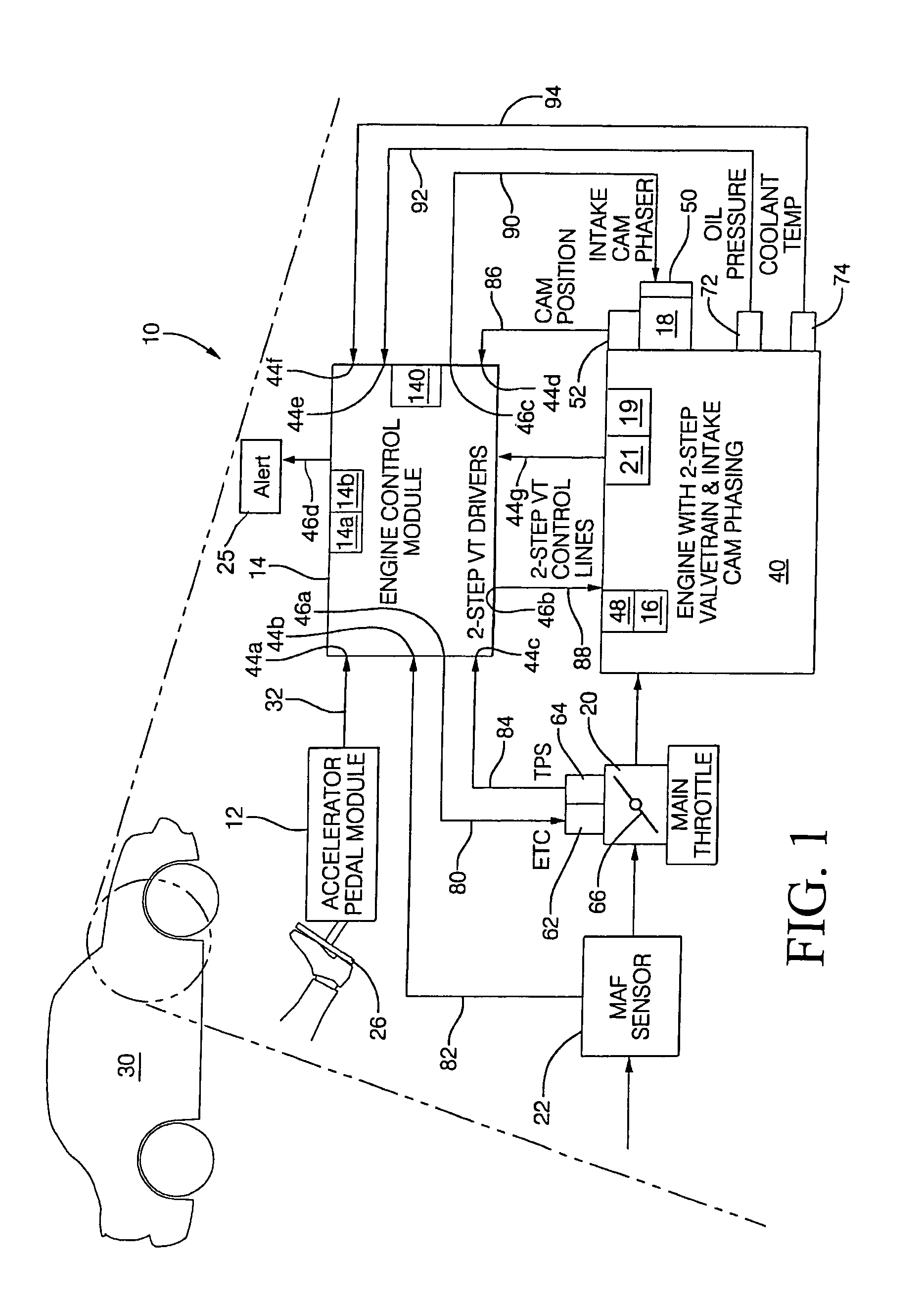
[0015]Generally, as will be described more particularly hereinafter, a method of the present invention is directed to maximizing the effectiveness of diagnosing the operational state of a variable valve lift device. On occasion, diagnostic systems may identify sufficient differences between a measured engine parameter and an expected engine parameter to indicate that the variable valve lift device may be operating improperly, but insufficient differences to conclusively determine that there is a problem. According to the present invention, the re-positioning of the camshaft to a phase angle relative to a crankshaft operates to increase the strength of a signal indicative of the operational state of the variable valve lift device so that the signal-to-noise ratio is increased, thereby achieving a higher degree of certainty and reliability when diagnosing the operational state of the variable valve lift device.

[0016]The method of the present invention may be implemented in using a sys...


PUM


Abstract

A method for diagnosing the operational state of a variable valve lift device (VVL) is provided. The method includes providing a first signal indicative of an estimated position of the VVL, the first signal having a first signal-to-noise ratio; determining that the first signal represents either a first condition indicating that the VVL is operating in one of two modes of operation, a second condition indicating that the VVL is not operating in the two modes of operation, and a third condition where the first signal is not in the first or second conditions; and adjusting a camshaft phase angle when the first signal is in the third condition so that the first signal has a second signal-to-noise ratio, wherein the second signal-to-noise ratio is greater than the first signal-to-noise ratio, whereby the operational state of the VVL is identified as one of the first and second conditions.

Description

TECHNICAL FIELD[0001]The present invention relates to a method for effectively diagnosing the operational state of a variable valve lift device; more particularly, to a method that effectively diagnoses the operational state of a variable valve lift device by changing a camshaft phase angle to maximize the signal-to-noise ratio of a signal indicative of the operational position of the variable valve lift device.BACKGROUND OF THE INVENTION[0002]Historically, the performance of an internal combustion engine has been limited by fixed valve lift profiles, i.e., fixed timing of the opening and closing of the valves relative to the angular position of the engine crankshaft and fixed lift of the valves. However, modern internal combustion engines may utilize one of several methods and / or devices to vary the valve lift profile to, at least in part, control the flow of gas and / or air into and / or out of the engine cylinders. Modern internal combustion engines may utilize devices, such as, for...

Claims


Application Information

Patent Timeline
IPC IPC(8): F01L1/34
CPCF01L1/022F01L1/185F01L1/3442F01L13/0036F02D13/023F02D41/221Y02T10/18F01L1/2405F01L2001/34469F01L2800/00F01L2800/11F01L2800/12F02D13/0207Y02T10/40F01L1/024Y02T10/12
Inventor WATERS, JAMES P.DARROW, JON C.
Owner DELPHI TECH IP LTD
Learn More