
Data storage cache system shutdown scheme

Active Publication Date: 2006-06-13
EMC IP HLDG CO LLC
View PDF13 Cites 112 Cited by
  • Summary
  • Abstract
  • Description
  • Claims
  • Application Information

AI Technical Summary

Benefits of technology

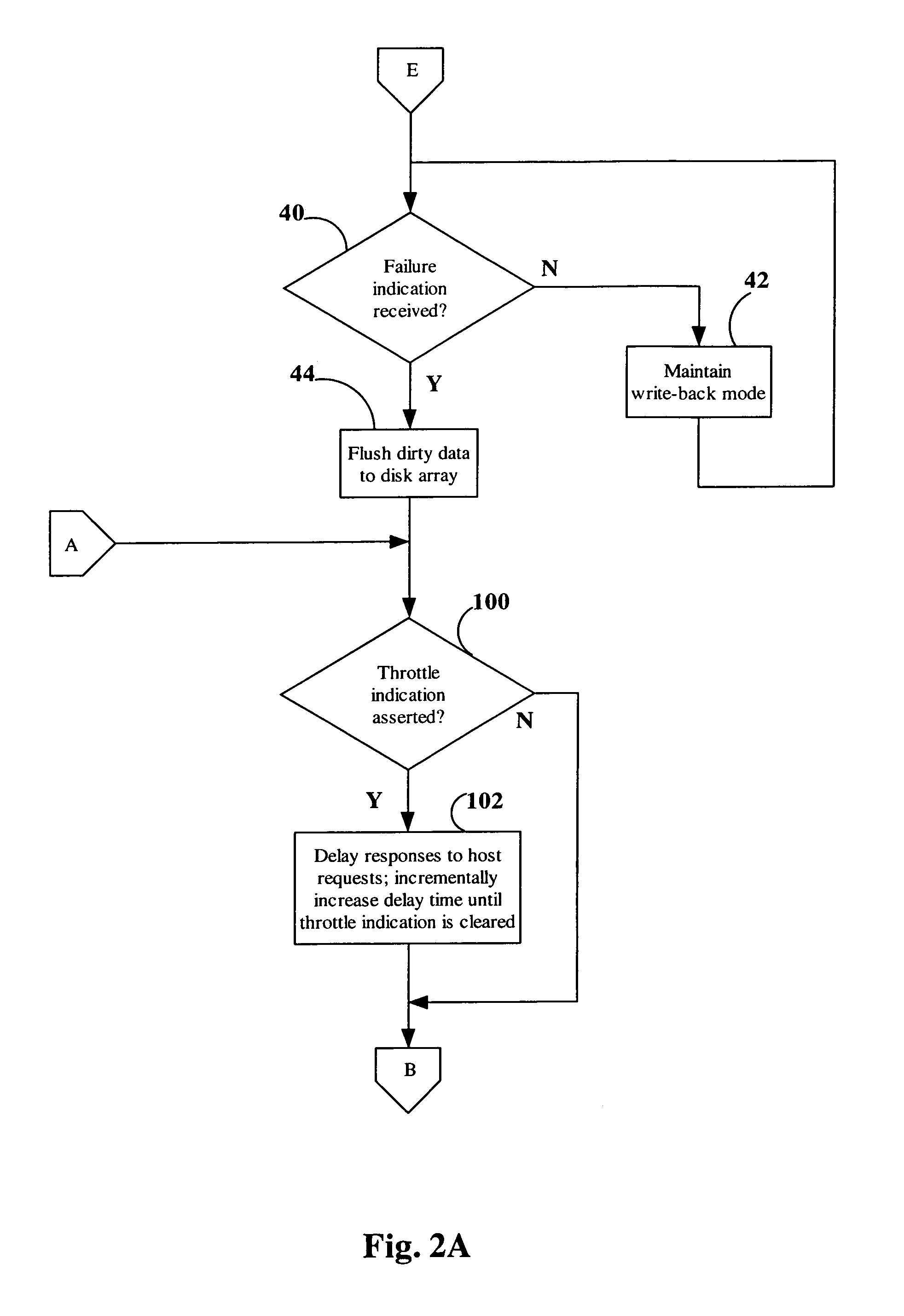
[0009]The controller may be further responsive to a throttle indication by delaying response times to host requests. This functionality is advantageous to ensure that the time spent responding to host write requests does not prevent the complete flushing of the dirty data within a given timeframe.
[0010]Similar methods and program products are provided. The invention is advantageously employed in a storage system in that loss of data is prevented during an impending failure, while host I / O activity can continue, thereby decreasing the likelihood that applications running on the host will fail. Impending failures often fail to materialize. The employment of the invention helps to make such non-materializing impending failures transparent to applications running on the host.

Problems solved by technology

These data storage systems may store very large amounts, for example terabytes, of data.
This can have devastating consequences where the application is, for instance, a database application supporting a financial institution.
Such write-back caching systems are vulnerable in a failure situation, since data that has been written to the cache may not yet be stored on the disk array.
If the cache system fails, the cached data may be lost.
This can cause an application to malfunction or fail.
For example, many storage systems contain uninterruptible power supplies or batteries that allow these systems to continue to operate for a limited period of time after a line power failure.
The halting of I / O activity to and from the host system is disadvantageous in that it can cause applications executing on the host systems to fail.
This is particularly deleterious in situations where the line power recovers before back-up power runs out.
It is very often the case that line power is lost for only a few seconds.
Thus, the currently known cache flushing mechanisms can needlessly cause applications to fail.

Method used


Image

  • Data storage cache system shutdown scheme
  • Data storage cache system shutdown scheme
  • Data storage cache system shutdown scheme

Examples


Embodiment Construction

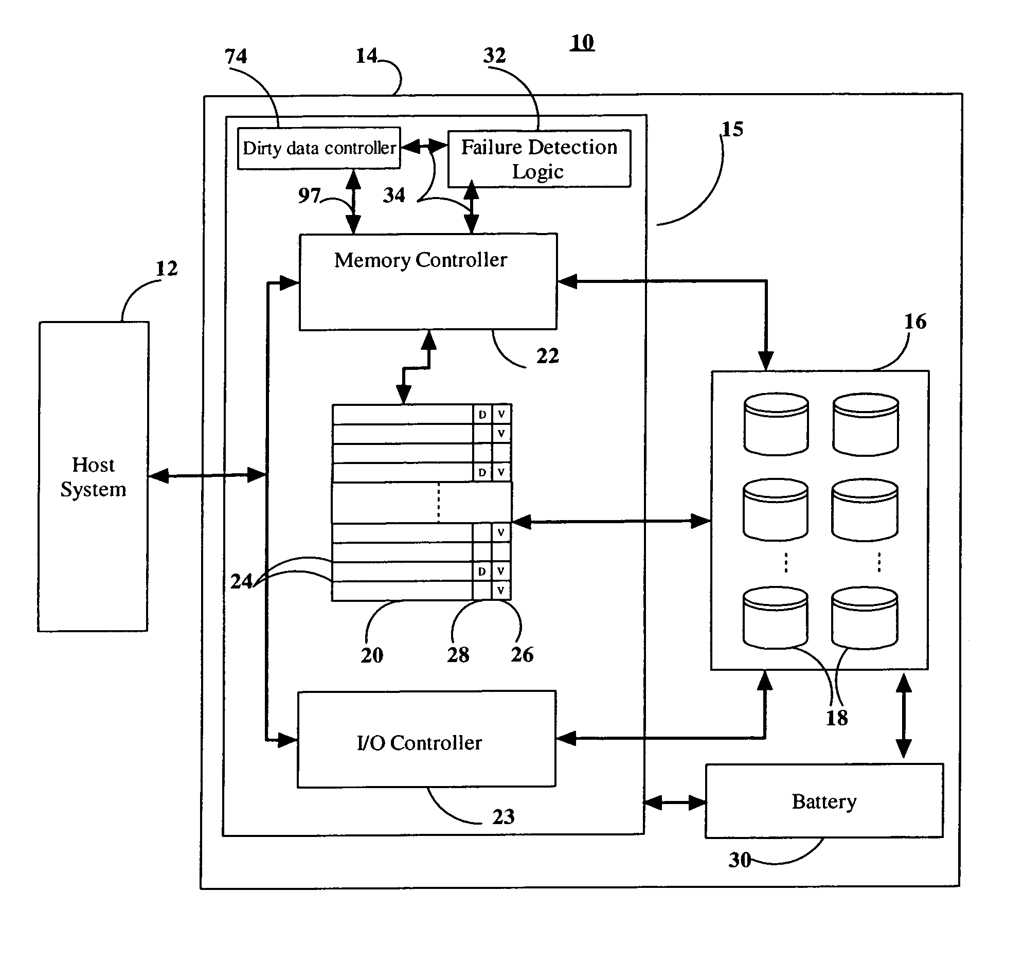
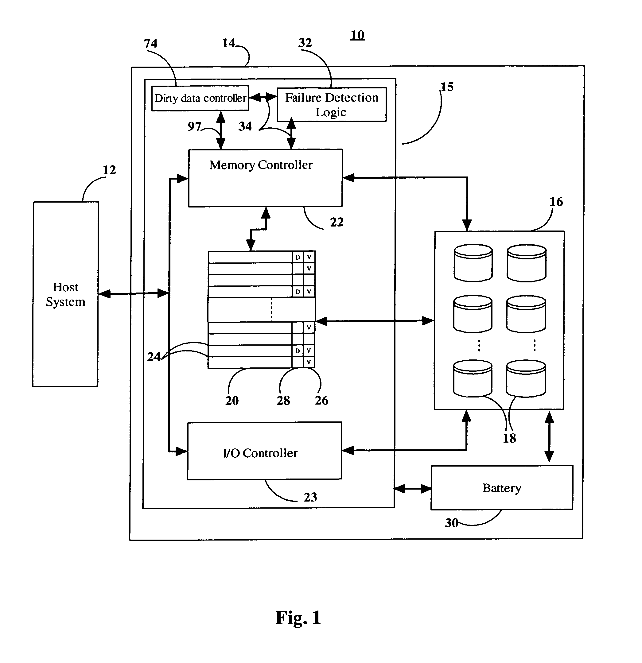
[0017]In FIG. 1 there is shown a computing system 10 wherein a host system 12 is coupled to a storage system 14. The storage system 14 includes a cache system 15 and a disk array 16. The disk array 16 is made up of banks of disk drives 18. The disk array 16 is in communication with a disk cache 20. A memory controller 22 is coupled between the disk array 16, the disk cache 20, the host system 12, and an I / O controller 23. The I / O controller 23 is further coupled between the disk array 16 and the host system 12. The disk cache 20 consists of memory, such as dynamic random access memory. Data can be accessed more quickly from the higher speed disk cache 20 than from the disk array 16. The capacity of the disk cache 20 is generally much smaller than the capacity of the disk array 16. For example, the disk array 16 may be capable of storing many terabytes of data, whereas the disk cache 20 may be capable of storing 512 gigabytes of data. The disk cache 20 is employed to store data read ...


PUM


Abstract

In a storage system including a write-back cache, dirty data can be flushed from the cache while a controller continues to service host I / O requests. A controller is capable of flushing all the dirty data in the cache to a storage device in response to an indication to do so, such as an indication of impending failure. The controller is further capable of responding to I / O requests from the host during the flushing of the dirty data. In particular, the controller is capable of responding to write requests from the host system by storing data on the storage device during the flushing of the dirty data.

Description

FIELD OF THE INVENTION[0001]The present invention relates generally to caches, and more particularly to techniques for flushing a cache during a cache system shutdown.BACKGROUND OF THE INVENTION[0002]In today's computing environments, data storage systems that include large arrays of disk storage can be connected to one or a number of host processing systems. These data storage systems may store very large amounts, for example terabytes, of data. It is important that this data not be compromised, and that it remains accessible to applications running on the host processing systems, because if an event prevents a host system from accessing the data on the storage system, the applications running on the host system can cease to function. This can have devastating consequences where the application is, for instance, a database application supporting a financial institution. Various mechanisms are therefore employed in data storage systems to prevent loss or inaccessibility of data.[000...

Claims


Application Information

Patent Timeline
IPC IPC(8): G06F11/00
CPCG06F11/1441G06F12/0804G06F12/0866
Inventor KEMENY, JOHN N.OHAMA, JUNSULLIVAN, DOUGLASMCCANN, PETER J.
Owner EMC IP HLDG CO LLC
Learn More