Multiple-directional switching valve

Active Publication Date: 2006-06-13
NABCO LTD
View PDF8 Cites 10 Cited by
  • Summary
  • Abstract
  • Description
  • Claims
  • Application Information

AI Technical Summary

Benefits of technology

[0007]The present invention has been devised in view of the above-described problems, and an object of the present invention is to provide a multiple-directional switching valve having a bucket-leveling function which can cancel the bucket-leveling function properly, have an excellent operation and a relatively short shape in its longitudinal direction.

Problems solved by technology

Further, the switching valve disposed in the diverged passage can block the oil flow from the rod-side chamber of the boom cylinder to the head-side chamber of the bucket cylinder, thereby canceling the bucket-leveling function properly.

Method used


Image

  • Multiple-directional switching valve
  • Multiple-directional switching valve
  • Multiple-directional switching valve

Examples


Embodiment Construction

[0022]Hereinafter, preferred embodiments of the present invention will be described with reference to the accompanying drawings.

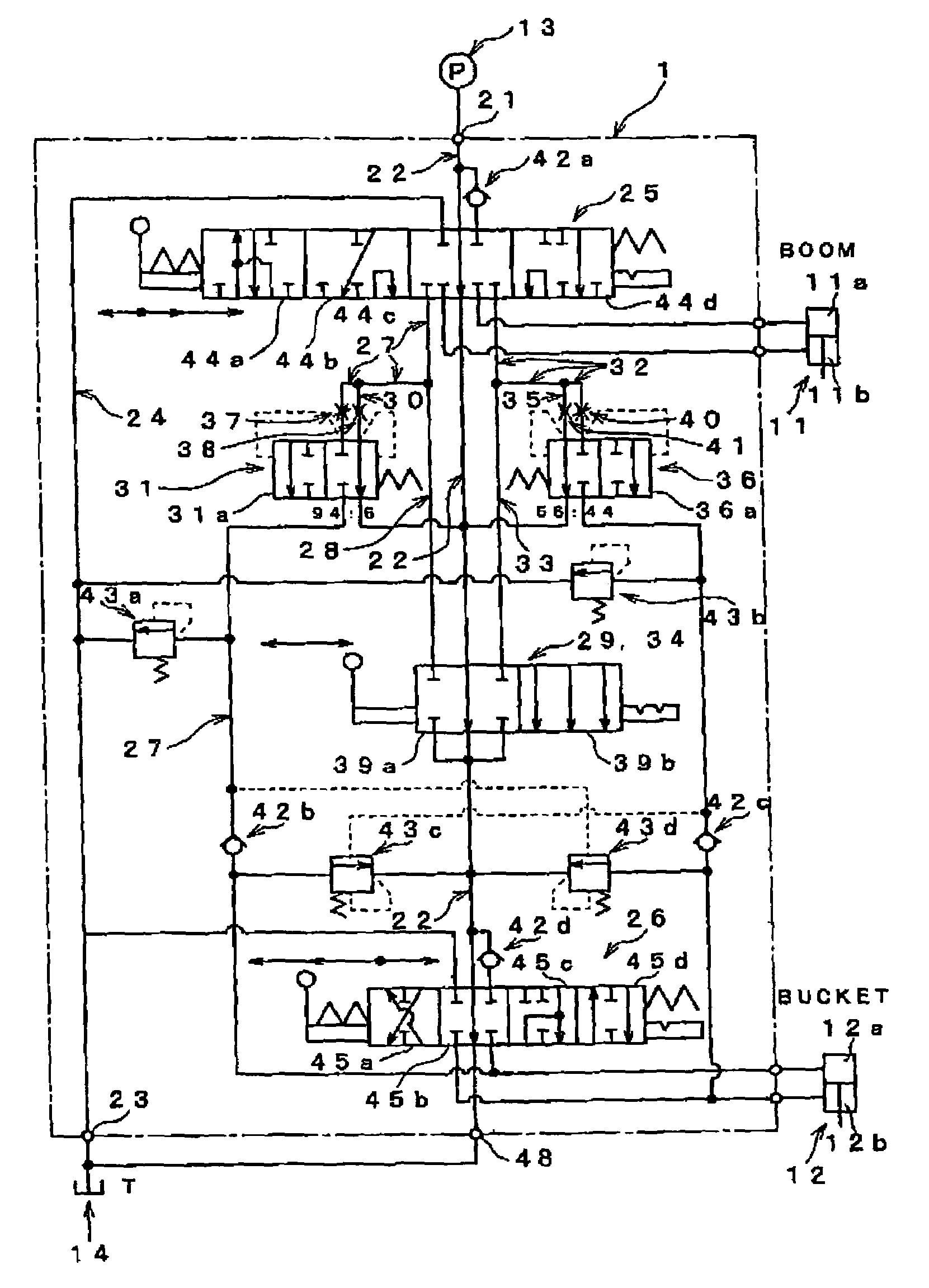
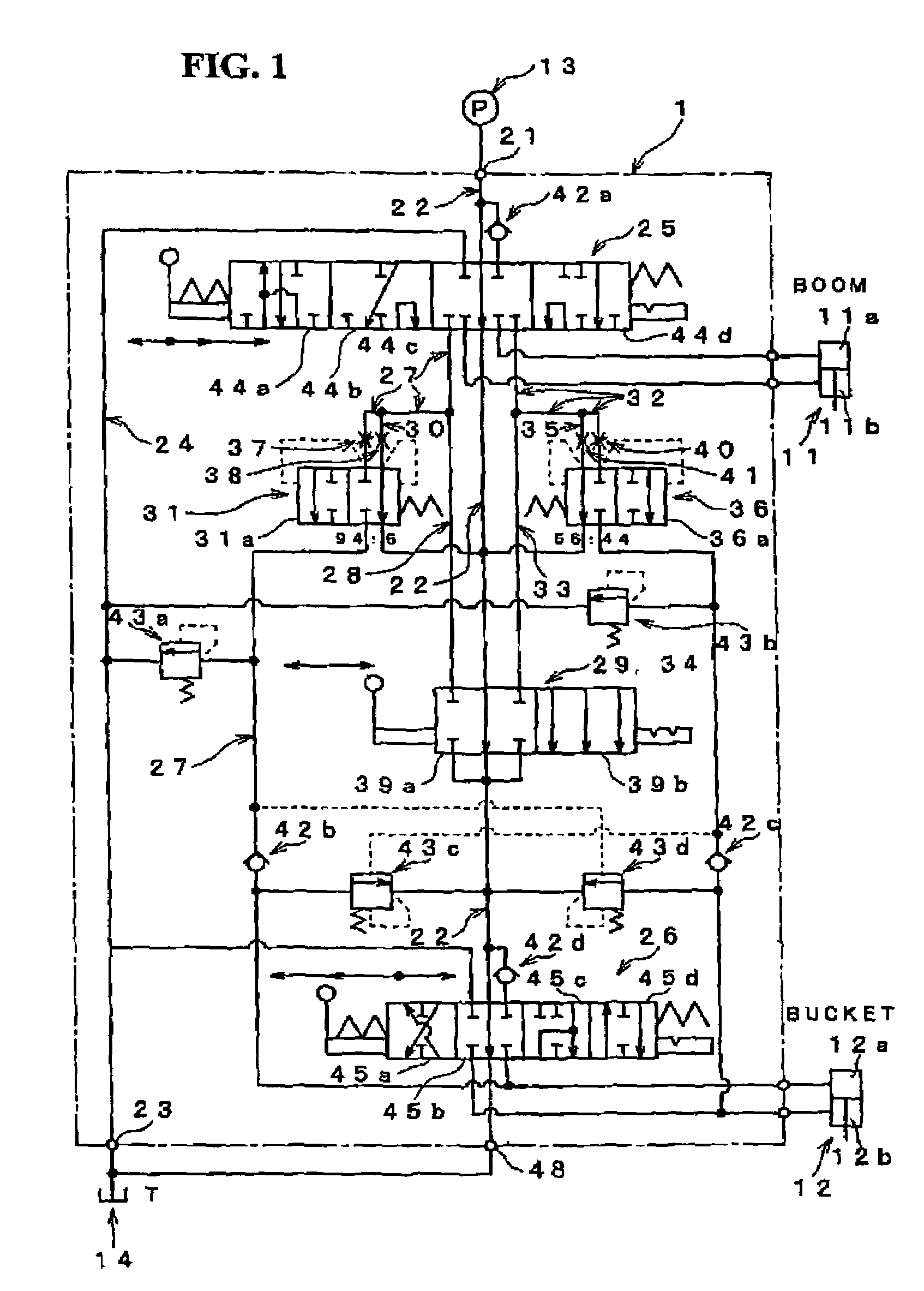
[0023]FIG. 1 is a diagram of an exemplified hydraulic circuit of a multiple-directional switching valve having a bucket-leveling function (hereinafter, referred to as “multiple-directional switching valve 1”) according to a preferred embodiment of the present invention. The multiple-directional switching valve 1 is used for a construction machine like a loader (not illustrated) which comprises oil-pressure operating devices, such as a boom (which is, for example, attached to a front of a loader so as to be raised and lowered) and a bucket (which is, for example, attached to a front end of the boom). The boom (not illustrated) is operated by a boom cylinder 11 in such a manner that it is raised by supplying a pressured oil to a head-side chamber 11a, while it is lowered by supplying a pressure oil to a rod-side chamber 11b. The bucket (not illustrated) is op...


PUM


Abstract

In a multiple-switching valve having a bucket-leveling function, there are provided a diverged passage, which is diverged from a merged passage and connects with an unloading passage or a tank passage, and a switching valve to disconnect and connect the diverged passage. The switching valve allows a pressured oil drained from a rod-side chamber of a boom cylinder via a directional switching valve for boom to be supplied to the merged passage flow in the diverged passage, thereby preventing the pressure oil from being supplied to a head-side chamber of the bucket cylinder. Accordingly, the bucket-leveling function can be cancelled properly, thereby improving the operation of the multiple-directional switching valve.

Description

BACKGROUND OF THE INVENTION[0001]The present invention relates to a multiple-directional switching valve which has a bucket-leveling function in which a bucket is maintained at a level position by supplying a return pressured oil drained from a boom cylinder to a bucket cylinder when a boom is operated by supplying the pressured oil to the boom cylinder.[0002]Conventionally, a multiple-directional switching valve which is used for a construction vehicle and the like and has a bucket-leveling function in which a bucket is maintained at a level position by supplying a return pressured oil drained from a boom cylinder to a bucket cylinder when a boom is operated by supplying the pressured oil to the boom cylinder. See, for example, Japanese Patent Laid-Open Publication No. 7-252857 (page 5, FIGS. 4 and 5), and Japanese Patent Laid-Open Publication No. 10-219730 (pages 4 and 5, FIGS. 1 through 3) (its corresponding U.S. Pat. No. 5,797,310). A hydraulic circuit disclosed in the former pa...

Claims


Application Information

Patent Timeline
IPC IPC(8): F15B13/00E02F3/43E02F9/22F15B11/16F15B11/20
CPCE02F3/433F15B11/20E02F9/2271E02F9/2267
Inventor IOKU, KENSUKENAKANO, JUN
Owner NABCO LTD
Why Eureka
Try Eureka