
Method for managing location information, related relay device and location information management device

a relay device and location information technology, applied in the direction of measurement devices, wireless commuication services, instruments, etc., can solve the problems of network traffic surge and communication network traffic surge, and achieve the effect of preventing network traffic surges

Active Publication Date: 2006-06-06
NTT DOCOMO INC
View PDF11 Cites 20 Cited by
  • Summary
  • Abstract
  • Description
  • Claims
  • Application Information

AI Technical Summary

Benefits of technology

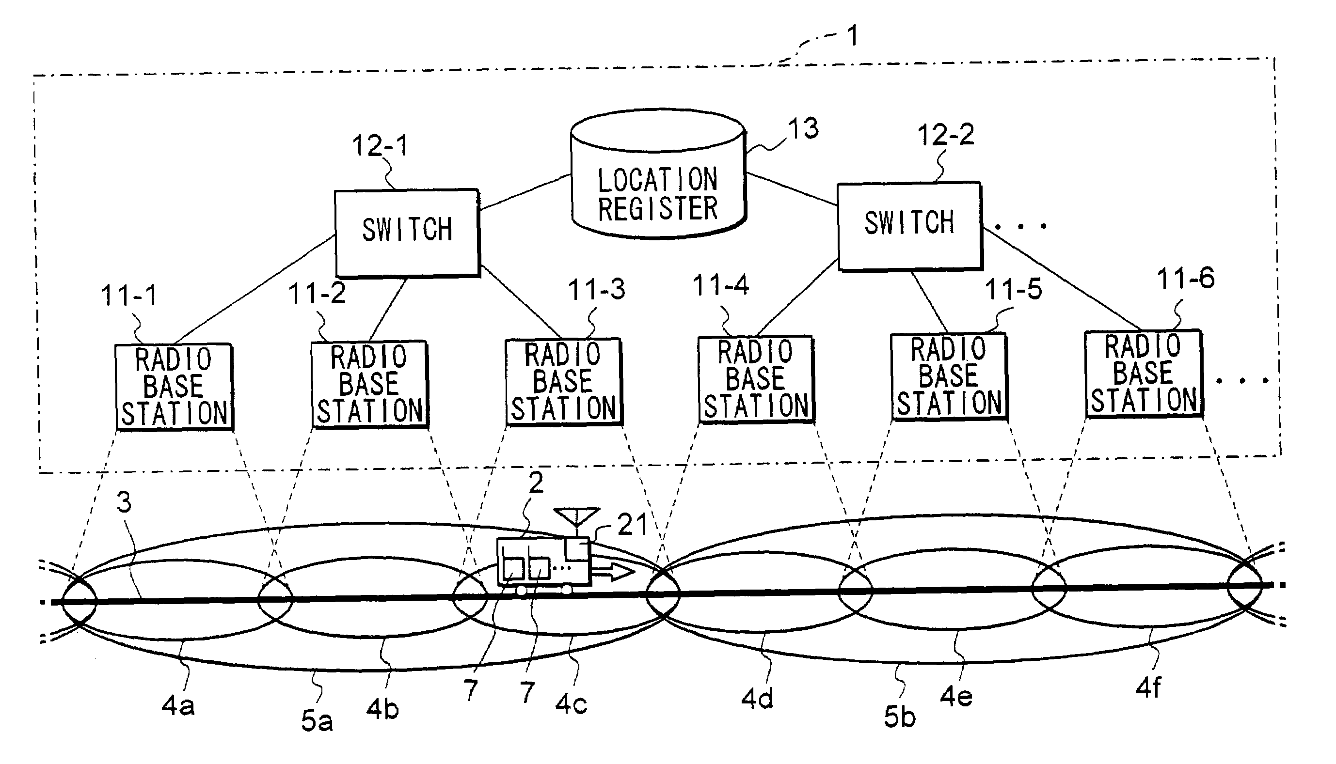
[0006]In view of the stated problem of the prior art, it is an object of the present invention to provide a method for effectively preventing surges in network traffic that would otherwise arise as a result of concentrations of transmission requests being transmitted by mobile communication devices when such devices move between location registration areas. A system related to the method of the present invention includes mobile communication terminals served by a mobile communication network.

Problems solved by technology

As a result, the communication network is subject to a surge in traffic.
However, a drawback of the system of the above publication is that in a case that a user of a mobile communication terminal disembarks from a train, it becomes necessary for the terminal to transmit a location registration request.
In a place such as a major station in a city where a large number of people may disembark at any given time from a train, a large number of mobile communication terminals may transmit location registration requests simultaneously, thereby leading to a surge in network traffic.

Method used


Image

  • Method for managing location information, related relay device and location information management device
  • Method for managing location information, related relay device and location information management device
  • Method for managing location information, related relay device and location information management device

Examples


first embodiment

A-2. Operation of First Embodiment

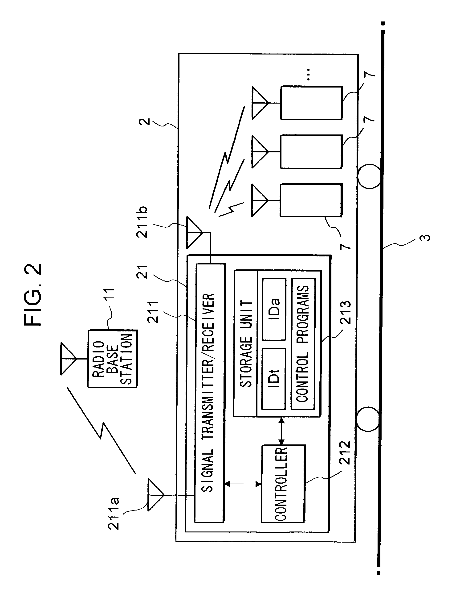
[0054]Operation of the first embodiment will now be explained hereinbelow. The following description will be given in three parts: (1) an operation of subordinating mobile communication terminal 7 to relay device 21; (2) an operation performed when relay device 21 moves from one location registration area to another in a state that a plurality of mobile communication terminals 7 are subordinate to relay device 21; and (3) an operation of discontinuing a master / slave relationship between relay device 21 and mobile communication terminal 7.

(1) Operation of Subordinating Mobile Communication Terminal 7 to Relay Device 21

[0055]It is assumed here that mobile communication terminals 7-1 (terminal identification information: “IDm1”) and 7-2 (terminal identification information: “IDm2”) are currently located in a location registration area 5a. Also, two mobile communication terminals 7-3 (terminal identification information: “IDm3”) and 7-4 (terminal identi...

second embodiment

B: Second Embodiment

[0075]Next, a second embodiment of the present embodiment will be described. Among elements in a mobile communication system of the present embodiment, the configurations of a mobile communication network 1 and a relay device 21 are the same as those of the above first embodiment, and therefore, explanation thereof will be omitted.

[0076]In the above first embodiment, a two-layer master / slave relationship is formed as shown in FIG. 5. In the present embodiment, a three-layer master / slave relationship is established as shown in FIG. 15. An example of such a relationship could include a ferry boat in the first layer (top layer), a carrier vehicle (e.g. a truck) accommodated in the ferry boat in the second layer (middle layer), and a plurality of mobile communication terminals 7 transported in the carrier vehicle in the third layer (bottom layer). Relay device 22 is installed in the carrier vehicle and moves to a subsequent location with relay device 21 which is inst...

first modification

C-1: First Modification

[0093]In the above embodiments, an operation of removing or changing dependency registration is triggered by a predetermined operation inputted to a relay device (21 or 22). However, the operation of removing or changing dependency registration can be independently performed by the relay device at predetermined timings. For example, assuming that the relay device is installed in a train, an operation for removal or change of dependency registration may be initiated by an event such as the relay device entering a predetermined region the center of which is a station. Examples are as follow:[0094](a) the relay device stores train schedules, and the operation is performed when a time is reached to move into a particular region;[0095](b) a center administering train schedules notifies that the train has moved into a particular region, and the relay device performs the operation upon receiving the notification; or[0096](c) a wireless communication device installed ...


PUM


Abstract

A location register 13 stores as location information of a relay device 21 to area identification information of a location registration area where relay device 21 is currently located and stores as location information of one or a plurality of mobile communication terminals 7 transported in a moving object 2, relay device identification information of relay device 21 to thereby subordinate one or more of a plurality of mobile communication terminals 7 to relay device 21. In the case that a master / slave relationship should be discontinued with some of a plurality of mobile communication terminals 7, relay device 21 transmits, to location register 13, a dependency registration removal request specifying the part of a plurality of mobile communication terminals 7. Location register 13 updates location information of the mobile communication terminals 7 specified in the dependency registration removal request to area identification information of a location registration area in which relay device 21 is currently located.

Description

FIELD OF THE INVENTION[0001]The present invention is directed to a method for managing location information designating an area in which a mobile communication device is located, and is also directed to a related relay device, location information management device, and a mobile communication system. More particularly, the method of the present invention enables location registration of a mobile communication device to be readily and effectively carried out in a mobile communication network.DESCRIPTION OF THE PRIOR ART[0002]In a well-known method for effecting location registration of a mobile communication terminal in a network, location information of, for example, a cellular telephone, is registered in a memory storage device (hereinafter referred to as a location register or a location information management device) provided in a node of a mobile communication network. Consequently, a mobile communication terminal in the network can be contacted regardless of a location registra...

Claims


Application Information

Patent Timeline
Patent Type & Authority Patents(United States)
IPC IPC(8): H04Q7/20H04M3/42H04W88/02
CPCH04W88/02
Inventor HIYAMA, SATOSHISASADA, KOJI
Owner NTT DOCOMO INC
Learn More