
Integrated micro-strip antenna apparatus and a system utilizing the same for wireless communications for sensing and actuation purposes

a micro-strip antenna and wireless communication technology, applied in the direction of resonant antennas, instruments, transmission, etc., can solve the problems of limiting the application of smart patches, structural degradation, and relatively expensive and difficult installation of smart patches into the structure, and achieve the effect of easy flushing

Inactive Publication Date: 2006-06-06
POLYTECHNIC INST OF NEW YORK +1
View PDF16 Cites 15 Cited by
  • Summary
  • Abstract
  • Description
  • Claims
  • Application Information

AI Technical Summary

Benefits of technology

[0007]An object of the present invention is to provide a wireless communication system which enables a number of predetermined characteristics of a structure to be detected and a signal indicative of such detection to be supplied from the structure in a wireless manner.
[0013]A further object of the present invention is to provide a multi-layer antenna apparatus which may be utilized to achieve a relatively high level of actuation by increasing the amount of power that may absorb. This arrangement of a plurality of microstrip antennas may be obtained by having several patches on a substrate or having several patches on several vertical layers integrated with the smart material.
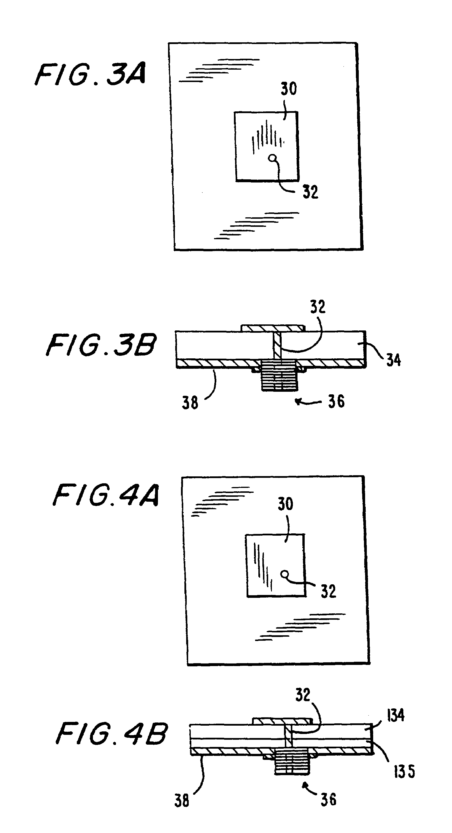
[0018]Microstrip antennas are relatively inexpensive and light-weight and may be utilized as radiating / receiving elements in radar and communication systems. Basically, a microstrip antenna may be fabricated by depositing / printing a small rectangular metallic patch on one side of a dielectric substrate, with the other side completely plated by a conducting plane. Such microstrip antennas may be fabricated in a variety of other shapes and sizes, such as those which may enable a microstrip antenna to be easily flushed mounted or arranged onto the body of a car, airplane, rotor blades, high speed machinery or the roof of a building. More complex geometries of microstrip antennas with multiple radiating elements, multiple substrate layers, or complex feed structure are obtainable as described herein so as to meet diverse design requirements. Such multilayer configurations can be integrated with electronics and other control circuitry on separate substrate layers that would allow advanced electronic beam steering, digital control and adaptive processing.

Problems solved by technology

As is to be appreciated, such use of power and / or signal lines may limit the application wherein smart patches may be effectively utilized, or may make the installation of smart patches into a structure relatively costly and difficult.
Furthermore, inclusion of wires and signal lines in a structure may cause structural degradation and therefore rapid fatigue.

Method used


Image

  • Integrated micro-strip antenna apparatus and a system utilizing the same for wireless communications for sensing and actuation purposes
  • Integrated micro-strip antenna apparatus and a system utilizing the same for wireless communications for sensing and actuation purposes
  • Integrated micro-strip antenna apparatus and a system utilizing the same for wireless communications for sensing and actuation purposes

Examples


Embodiment Construction

[0034]Preferred embodiments of the present invention will now be described with reference to the accompanying drawings.

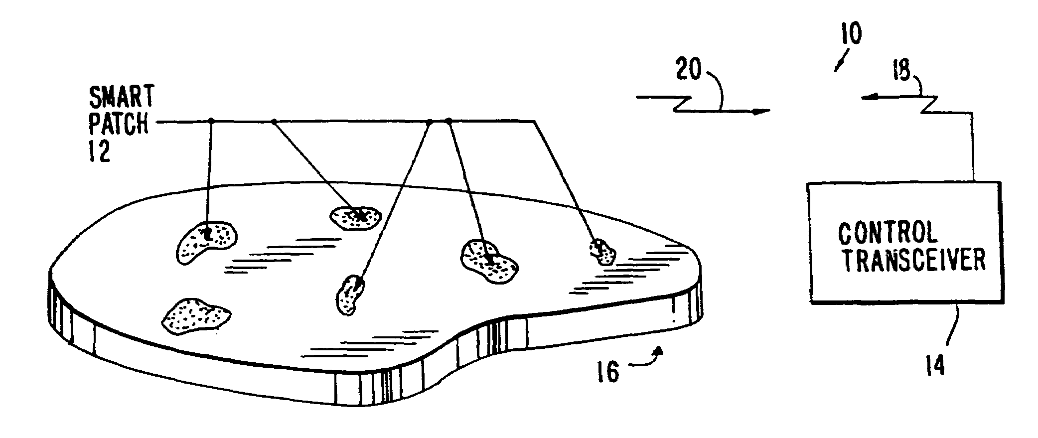
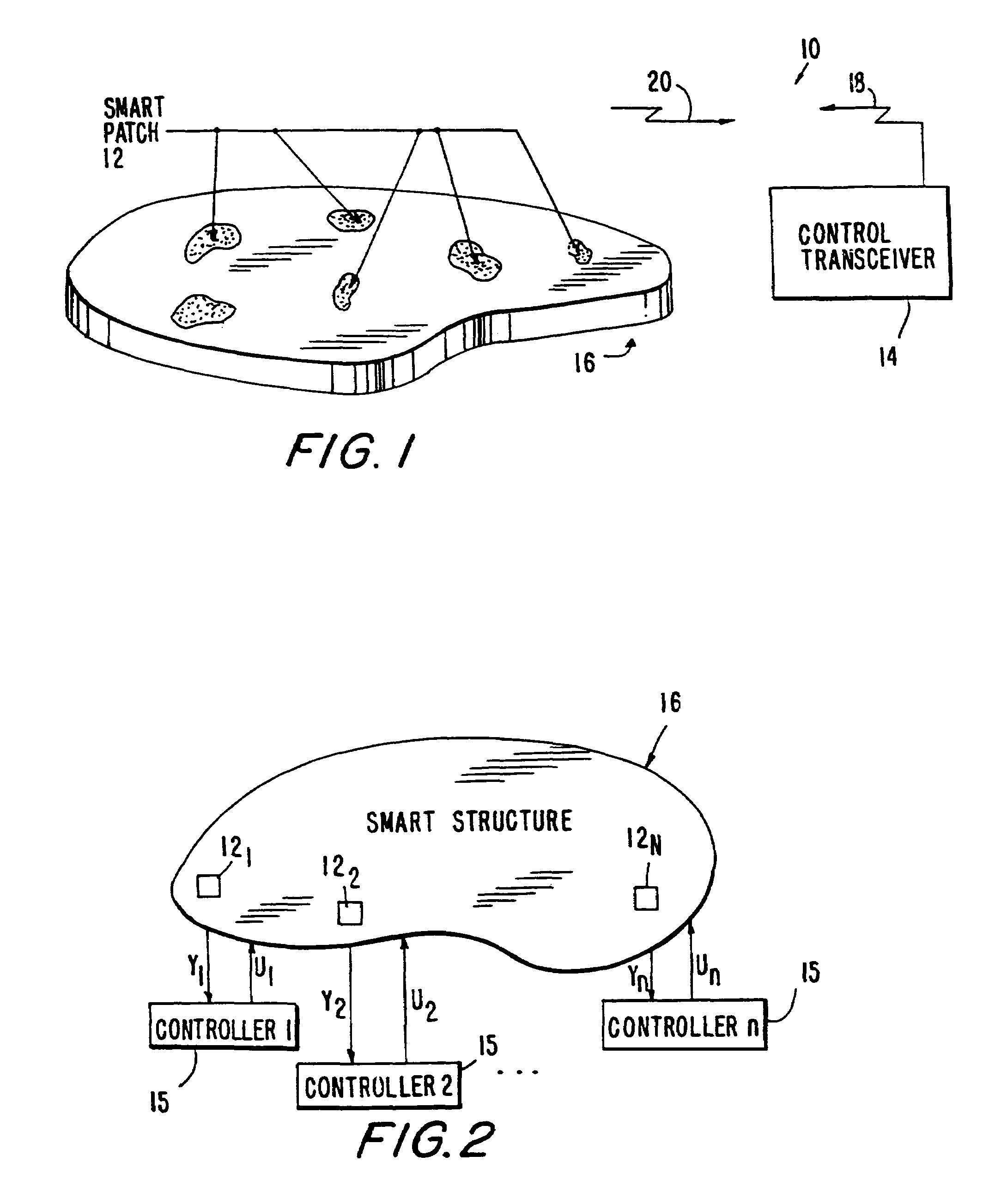
[0035]FIG. 1 illustrates a smart structure communication system 10 consisting of a smart structure 16 which includes smart patches 12, such as those shown in FIG. 5 (i.e., an integrated set of sensors, actuators, electronics, signal processing and control hardware, and micro strip antennas). The smart structure communication system also contains a wireless transceiver system 14 which is adapted to communicate with the smart structure through a transmitting signal 18 and a receiving signal 20. The sensors and actuators in the smart patches 12 may be of active or smart materials such as piezoelectric ceramics. However, other active materials may be used such as electrorestrictive, shape memory alloys, ferro-electrics, bio-polymers and so-forth.

[0036]FIG. 2 illustrates the smart structure 16 with the associated smart patches 12 and feedback controllers 15. Each of the ...


PUM


Abstract

A system utilizing a number of micro-strip antenna apparatus embedded in or mounted on the surface of a structure for enabling wireless communication of sensed and actuation signals. The micro-strip antenna apparatus may include smart materials or other substrates. If only a sensed operation is desired, the micro-strip antenna apparatus may be fabricated from only passive elements or materials. Furthermore, a micro-strip antenna apparatus is provided which enables simultaneous transmission / reception of sensing and actuation signals.

Description

[0001]This is a Continuation of application Ser. No. 08 / 806,565, filed Feb. 25, 1997, now U.S. Pat. No. 5,970,393.BACKGROUND OF THE INVENTION[0002]This invention relates to a micro-strip antenna apparatus and a wireless communication system utilizing such apparatus. More particularly, this invention relates to a micro-strip antenna apparatus having a number of antenna elements and arrays integrated with substrates of smart materials, such as piezoelectric devices, and to a system employing such apparatus for enabling wireless communication to and / or from smart structures.[0003]A so-called smart patch may be surface mounted or embedded in a structure (such as helicopter rotor blades, high-speed machinery, and so forth). Such smart patch may include a sensor or sensors, an actuator or actuators, associated electronics, and / or a control circuit. A structure containing one or more smart patches is referred to as a smart structure.[0004]Smart patches in a smart structure may operate as s...

Claims


Application Information

Patent Timeline
Patent Type & Authority Patents(United States)
IPC IPC(8): H04B7/00H01Q3/44H01Q3/46
CPCH01Q3/46H01Q3/44
Inventor KHORRAMI, FARSHADDAS, NIROD K.
Owner POLYTECHNIC INST OF NEW YORK
Learn More